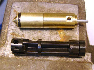
The stock valve assembly and piston.
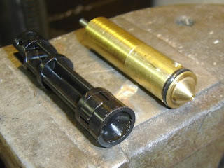
Notice the conical end of the valve body, and the conical seal on the piston.
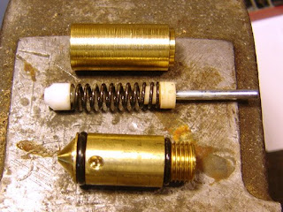
The valve was disassembled. Notice the very rough turning on the valve body!
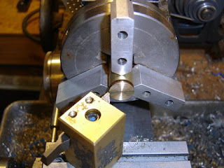
Facing the end of the valve intake end.
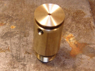
Nice and flat with a fine finish.
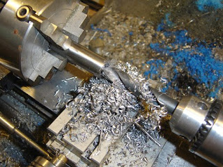
Drilling out a piece of 5/8" free machining steel, after turning it down a few thou.

Tapping it 1/2"-20 by hand, aligned on the lathe.
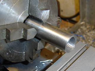
The finished thread. I then flipped it around and finished the other end to the same diameter.
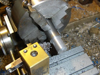
Turning down another piece of steel to 1/2" (minus about 10 thou).
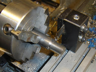
I threaded it by hand using a die. No pics of that as I was cursing and sweating all the while. I now have a note "Buy good quality 1/2"-20 tpi die" on my to-do list. I then made a relief groove with the parting tool. Too much chatter.
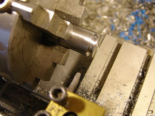
I ground a radiused tool to do the o-ring groove on the other end. I found I got the best control by rotating the chuck by hand as I plunged the tool into the work a few thousandths at a time.
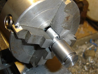
I put some aluminum sheet around the threads to protect them from the chuck and turned down the body a few thousandths and deburred everything.
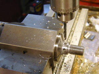
Drilling six radial holes to allow adjustment. This turned out to be wholly wrong, I needed at least eight holes to easily adjust the piston when assembled in the carbine. Live and learn.
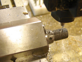
Making a 3/16" dia pocket in the threads.
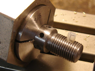
A piece of nylon rod was pressed in and then cut off to the thread diameter. This allows enough interference so that the adjustments don't become undone. The Daisy 717 uses a similar nylon patch.
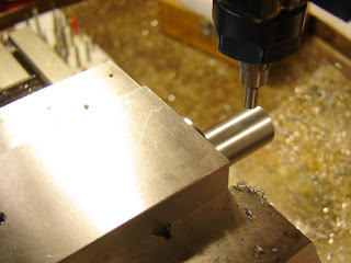
I used an edge finder (I use them often on these projects, did you know that I sell them?) to find the centerline of the rod and the end.
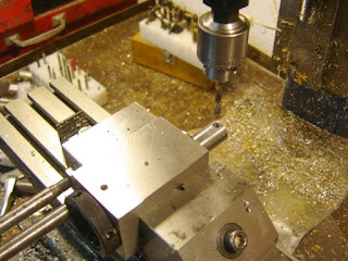
Drilling the pivot hole.
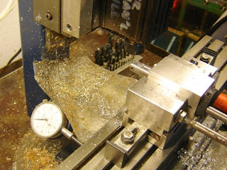
Milling the slot halfway through on each side. Notice the use of a dial indicator to keep the length of the slot consistent.
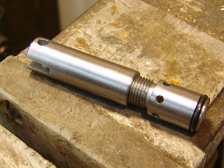
The finished adjustable piston.
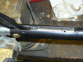
And mounted in the carbine. I only needed to adjust it about 1/8th of a turn to get it to touch the valve face. Notice the adjustment hole problem...
Anyway, the reason for making the new piston was to both increase the rigidity of the piston and to eliminate excess headspace, thus pushing more air into the valve on each stroke, yielding slightly higher pressures. Pumping effort did not increase, although there's a small amount of vacuum that needs to be overcome on the return stroke.
Using the chronograph I found that I got the following averages:
Before:
3 pumps: 421 fps
5 pumps: 523 fps
10 pumps: 645 fps
After:
3 pumps: 450 fps
5 pumps: 568 fps
10 pumps: 724 fps
Crosman Premier Light pellets, 7.9 grains, were used for all tests.
4 comments:
Cool piston! Just a couple questions. What O ring did you use and what were your slot dimensions? Any particular reason you used steel inatead of brass?
Do you think a 5/8 SHOULDER BOLT would work? I know it has a 1/2 11 not a 20 but I have a few lying around.
Good Job!
AJ
I basically just cut it to almost the diameter of the o-ring, and kept removing it and trying it until I got what felt like a good fit. Width was slightly more than the width of the o-ring, to allow a slight squish.
As for a shouldder bolt? Should work fine.
I used steel because I didn't have any brass, I felt plastic would be too flexible and aluminum might gall against the steel of the tube. But most of all because I have a bunch of 5/8" diameter steel.
I don't understand the purpose of being able to adjust the length of the piston, why not just build it to the right length to eliminate headspace?
The reason is too many variables and changes over time. Things stretch and wear.
Post a Comment