Crosman has been using a new two-stage trigger compatible 22XX grip frame for a while now but only installing the simpler single-stage trigger parts. So, if you have the new style grip frame (or buy one) and want to upgrade to a true, two-stage, fully adjustable trigger for your 22XX style gun, it's possible to order the parts directly from Crosman. Looking around online, I found a few tutorials on how to make the parts retrofit, but most glossed over the problems I ran into. Anyway, here's the details of my conversion and the minor headaches you'll experience if you go down this road.
This is my original old-style 2240 single-stage grip frame and trigger components. The cover plate is diecast and held by two screws. This grip frame will NOT fit the new two-stage trigger parts.
Here is a new style grip frame and the necessary two-stage trigger parts. The cover plate is plastic and held by three screws. These three screw frames will accept either single or two-stage trigger components.
The first problem I ran into was my grip frame did not have a hole to reach the set screws to set up and adjust the new two-stage trigger. I don't remember where I got this grip frame--it's probably from a 2300S. It's likely that this hole will not be drilled in the new frame if the gun is sold with the single-stage trigger set up.
Spotted and drilled a 1/4" hole.

I also spotted, then drilled, for a trigger stop using a #29 bit.
Some small taps.

A pin vise gave the necessary extension to cut the #8-32 thread.

A #8-32 set screw and a drop of loctite and the frame is now ready to go.
With the frame prepped, I could start assembling the two stage parts. For a list of the necessary parts I went to Crosman's site and
download the EVP for the Crosman 1701P pistol. I called Crosman with the part
numbers and ordered everything on the grip frame schematic that I didn't
have.
So here's how it all goes together. Starting with the trigger:
Install the safety and then the trigger with the two adjustment set screws and trigger pivot pin. Initially, I used teflon tape on the threads of the set screws. This was a mistake. Use a medium strength loctite instead.
Install the trigger spring.
It goes over the link pivot boss. Note the lower leg sits on top of the trigger between the two set screws.
Now the trigger link:
Install the link and link pivot pin. Note that the upper leg of the trigger spring is on the underside of the link. Click on any picture to enlarge.
The spring adjuster assembly was next:


Link spring goes in the housing.
Push it all the way though.
The tail is captured in the counter bore.
The brass adjuster screw threads through the spring using the coil itself as the thread.
It's threaded all the way through like so.

Then the tiny #0-80 locking screw is threaded into the end of the brass adjuster.
Install the adjuster housing assembly:
Hook the end of the spring to the trigger link.
The post in the grip frame holds the adjuster assembly in place.
The sear is last:
The sear spring is installed in the top of the adjuster housing.
The sear is then installed. Tab at the bottom of the sear goes into the spring, then the sear is swung into place and onto the sear pivot pin.
The cover then goes on and I thought I was done. Nope. The new trigger is a huge pain in the ass to adjust. With the cover in place, the adjustments to the trigger set screws are blind. Removing the cover made the spring loaded components pop out of place and onto the floor. It's 2019. This is supposed to be easy. Took a que from a feature Crosman used (in the mid 1950's!) on the trigger housing for the 160 CO2 rifle.
Removed the side plate and with a 5/16" endmill, I cut a hole--to see what the set screws were doing against the link.

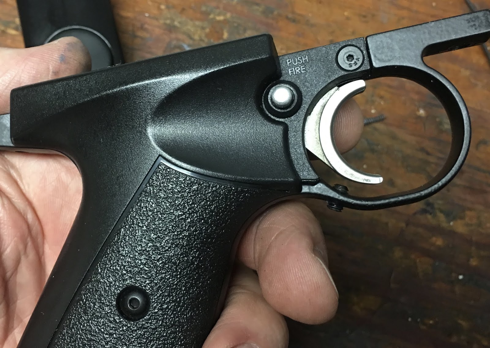
The hole is pretty much in line--and just behind--the safety hole. I did make sure the grip would just cover the hole. This COULD be done on the other side in the metal grip frame--but if you screw up, remember that it's more expensive to replace the metal frame than the plastic cover...
Like a window into my soul.
I really can't believe this isn't done at the factory. Anyone have a Benjamin Marauder pistol? Is there a hole in the grip frame or the cover?
A quick test fit shows the hole is covered by the stock Crosman grip panel.
The trigger set screws require a 0.050" hex wrench. I found that a Bondhus hex driver worked perfectly.
With the grip frame installed, the window made it easy to adjust the two stages perfectly. The front screw adjusts the length of the first stage. The rear screw, the second stage. I wanted the first stage relatively long and with a solid "wall" when it transitioned to the second stage, then just a bit more pressure (but no perceived travel) to fire. To do that, I screwed the front screw in further than the rear and played with the adjustments while cocking and dry firing the pistol. Backing out the link spring tension adjuster also let me dial in the feel. When finished, I adjusted the trigger stop so the trigger stopped cold at the moment of firing.
A couple more snags:
First, while the stock Crosman/Benjamin plastic grips are good to go, most custom wood grips will NOT fit without additional inletting. The adjuster housing body stands proud on each side of the frame, so a wood grip will not seat flush to the frame without adding some extra clearance.
Second, a stock 22XX hammer will ONLY work if you pull and hold the trigger to the rear while cocking the gun. With the bolt pulled completely to the rear, let go of the trigger and the sear will catch. Yeah. Great. I've read that the hammer from a Crosman 1701P will solve this problem. I've also read that a 1701P hammer will ONLY work in the 22XX gas tubes. It's too large in diameter for the smaller 13XX compression tube. So there's the warnings.
Of course, I found out about the hammer after I'd ordered all the other pieces parts from Crosman. Rather than another order and another week for delivery, I made a couple new hammers.
That'll be the next post.