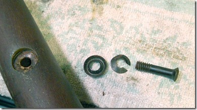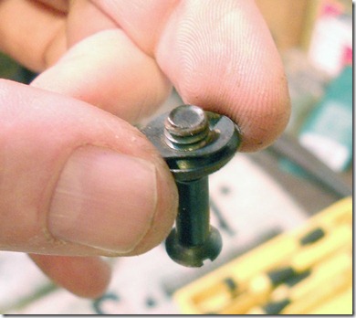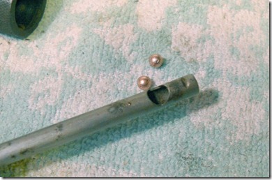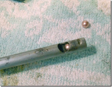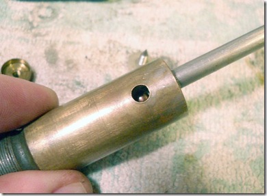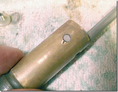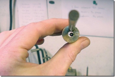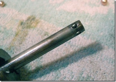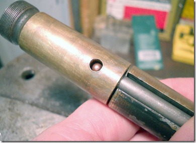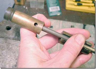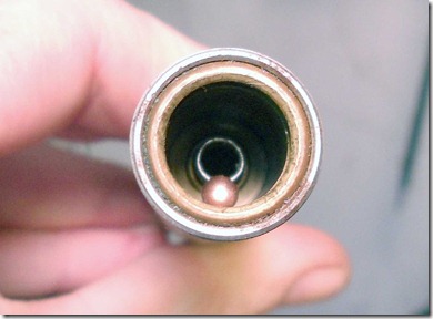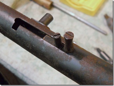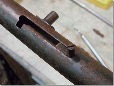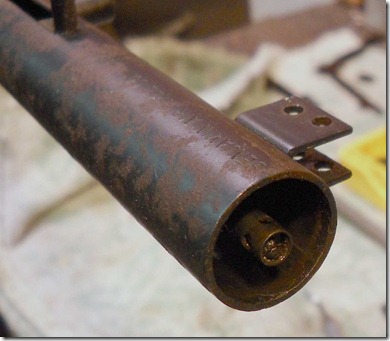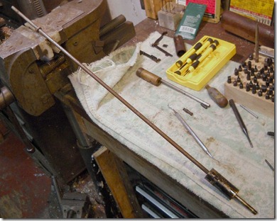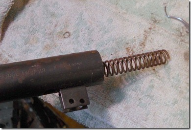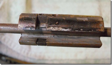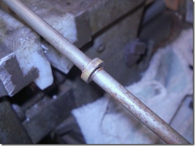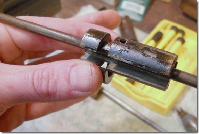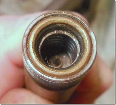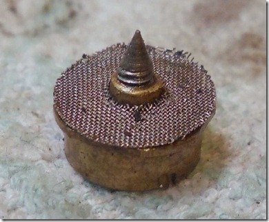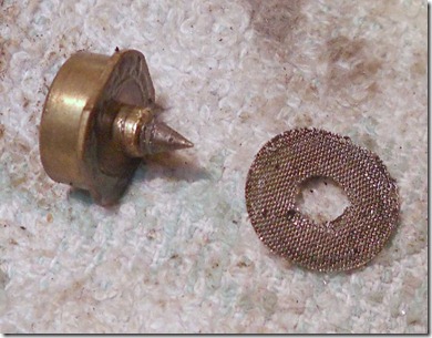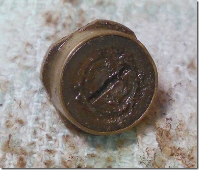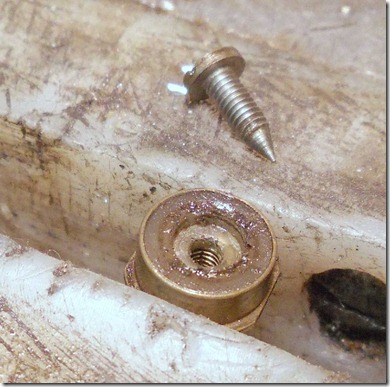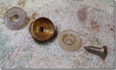
Shot the gun until empty of CO2. Removed the trigger shoe, safety lever, stock nut and "locating stud"--to use the old Crosman lingo for the part.

The QB locating stud is double threaded. M6 x 1mm at the valve end, M7 x 1mm at the nut.

The hole through the stock is about 5/16", and since the gun is made in China it's safe bet they used an 8mm bit.

Forstner bits

A 5/8" is close (or maybe even the same) to the diameter of the counterbore for the washer and stock nut.

Clamped the stock to the drill press table and aligned by guesstimation and pure, unadulterated luck.

Deepened the factory counterbore.

Ran the forstner bit at a fairly high speed to help prevent tear outs in the wood. The bit also needs to be nice and sharp for a clean cut.

Probably a good idea to treat the bare wood with something.

Looks like a pretty good match. After it dried, I gave it a good slathering of Danish oil.

Need to make a couple parts--a screw cup to fit into that counterbore as well as a new locating stud. Gonna use a piece of aluminum for the cup. Normally, I'd use steel and blue it, but polished aluminum will work since the stock sports an aluminum Morgan buttpad. Found a scrap of aluminum rod buried on the workbench.

Turned down one end to 0.621". Dang.

I wasn't paying attention and missed my (self-imposed) target diameter by 0.004". Flipped the piece around and turned the other end to 0.625".

Second time was the charm. Spotted for a through hole. Set the piece aside and switched to making the new stud.

I'm going to take advantage of the 8mm through hole in the stock. Since 5/16" is almost exactly 8mm, I cut the head off a long 5/16" bolt and faced the end.

Threaded one end M6 x 1mm to fit into the valve. Original stud is below. Cut the thread to length.

Cut down and faced to OAL. This is the gun stock end of the stud.

Spotted-n-drilled with a #19 bit about 3/4" deep.

Tapped M5 x 0.8mm. Cut a shoulder at the base of the M6 (valve end) thread. The shoulder was cut to 7.09mm diam.

Back to the aluminum screw cup. Through drilled.

Then drilled a countersink for the head of a M5 bolt.

Locating stud.


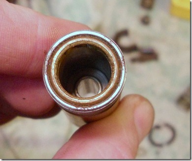
Installed. That shoulder is a nice tight fit in the hole through the gas tube --the valve won't ever shift backwards under gas pressure.

Another view. You can see the M5 x 0.8mm threads in the stud.

Sits just below the bottom of the counterbore in the stock. The new 5/16" diameter stud is a snug fit in the through hole. Much better fit than the stock stud.

Left the screw cup a few thou long for fitting to the contours of the forend. A bit of dykem layout fluid...

and the cup is pressed home. Used a scribe to trace around the cup where it stands proud.

Should have used the drill press and a tiny sanding drum, but it was 10PM and I didn't feel like going out to the garage. Yep, lazy. Used a cratex wheel in the Dremel. You can see the scribed line in the dykem.

Getting there. Marked the inside of the screw cup. No way are the stock contours symmetric, so the cup is actually directional.

Sanded to just below the line. A test fit showed a high spot here and there. The cup was gradually worked down until I was satisfied, then sanded out and polished.


Don't think the bolt head is finished to the same degree as the cup. I'll polish it and re-blue when/if I refinish the stock.

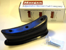
It blends well and matches the polished aluminum plates on the Morgan perfectly. Most importantly, my offhand is happy again.
