Saturday, June 20, 2009

Slavia Model 630 Disassembly, Part 2

On I go.

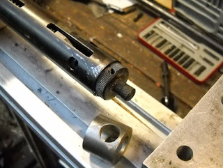
Rather than just remove the end plug I mounted it in the spring compressor.
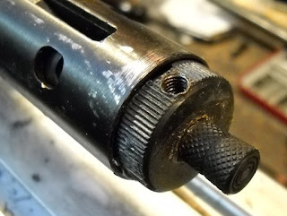
There was nothing in that threaded hole, and I'm not sure why it's there.

I used a spacer so the force of the compressor would bear on the plug and not the safety.
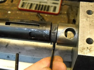
Using an allen key in that threaded hole to unscrew the plug. I would unscrew a turn, back off the compressor, rinse and repeat.

It came out about this far once unthreaded.
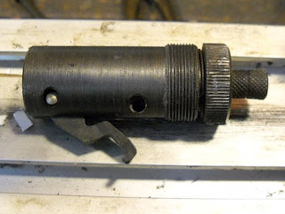
The sear hangs down and is held by that pin.
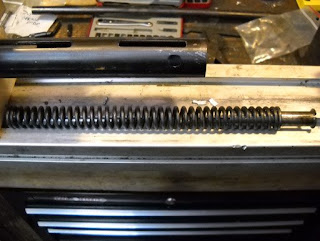
The spring and guide. There was no spacer as shown in the webpage I linked to in part 1.
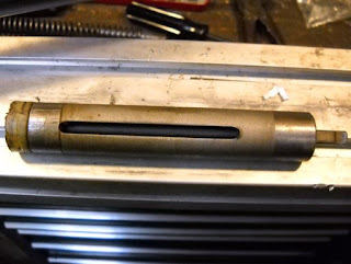
The piston.
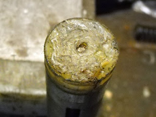
The seal has definitely seen better days.
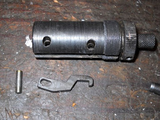
The sear removed.
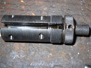
A coil spring retains the safety.
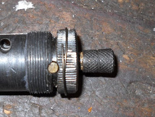
I slid it off and pulled out that pin with pliers.
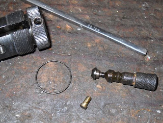
Then pulled out the safety. The other 630 is missing the safety and I'm not sure whether or not the rifle will work without it. I'd rather not make a duplicate of that.
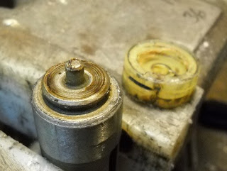
I pried the seal off the piston. Finding replacement seals is tough. An email to CZ in the Czech Republic was unanswered. I found a Canadian airgun store that does sell replacement seals but they don't ship to the U.S. I have to convince my sister in Toronto to order some for her nut of a brother. But I'll probably have to make at least one seal in the interim.
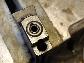
The breech seal was also in poor shape. But it's just an o-ring.

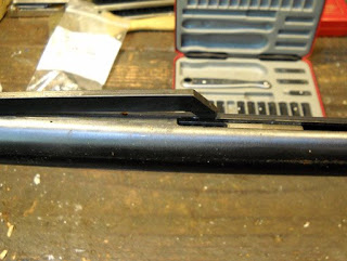
I unscrewed the sight elevation set screw.
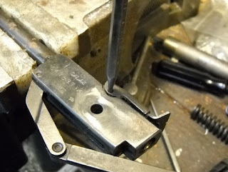
And punched out the pin.
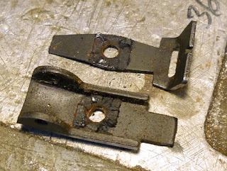
A neat design. The leaf tensions the sight but pivots left and right for windage. Minimalist. Not sure what the rubbery stuff is - rubber probably. No front sights were on the rifles.
So that's it all apart. Not sure when I'll work up the enthusiasm for making a replacement seal...
Friday, June 19, 2009

Slavia Model 630 Disassembly, Part 1

I bought a pair of beater Slavia model 630 rifles a while back. One is in worse shape than the other but they're both pretty tired. There's already an excellent tune article up but I figured there's nothing wrong with supplying more information.

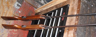
The two rifles. Sorry about the lack of composition...

Remove two screws from the stock forearm.

And the rear trigger guard screw.

When you remove the stock a small bent piece of steel comes out.

That fits in here.

It keeps tension in the cocking arm.

The cocking arm. Most (many?) spring piston airguns have a cocking arm with ears so that it is retained in the slot, but not this Slavia.

It just lifts out.

I broke the barrel to relieve tension on the hinge pin.

I removed the lock screw and then the pivot bolt.

You can see a notch in the chisel detent. It is rotated 180 degrees and the slot fits over the pivot screw to retain it.

Spring and detent slide right out.

You can see how the pivot hole intersects the hole for the detent.

This pin retains the trigger.

It pushes out with a pin punch.

And you rotate the trigger out.

Don't lose that spring...

Tuesday, June 16, 2009

Modified Piston for a Beeman P17

Feeling under the weather and didn't take pics as I worked this project along. Sorry everybody. Nick thought you'd all follow along just fine so I'll go with what I've got.
If you've read all the P17 posts here, you may remember that I modified a P17 piston with a second o-ring to fix the durability issues that the gun is known for.

At the time, I also wondered if there were any gains to be had by making the piston adjustable in length. Could the piston be adjusted to compress more air into the valve?

I'd already finished the project when I took these pics. Up top is a piece 1/2" diameter water hardening drill rod. I cut a 4.1" piece off and turned the ends flat on the Taig lathe. Next, I reduced the diameter of one end of the rod to 0.472"over 2.590". The 0.472" diameter is necessary to fit snugly in the channel on the P17's lower grip frame. Drilled a hole 3.2mm in diameter in the reduced end.

Cut 0.900" of threads on the other end 1/2" x 13 tpi. Drilled the cross pin hole, threaded for the M4 set screw and called it good. Absolute length measurement was not at all critical, but for the record, it's 4.052" OAL.

Here's a pic of the piston I started this project with.

Cut the head of the piston off the original one-piece affair. Made it 1.825" long. Length not critical. Drilled a hole part way through the piston (0.940" deep actually) and tapped a matching 1/2" x 13 female thread.

Did a couple secondary machining steps to the piston head. Spotted, then drilled 6 holes around the circumference of the piston. These holes are accessible at the bottom of the compression tube after the piston is installed. They allow a short tommy bar to be inserted into a hole and the piston head threaded up or down the steel rod changing the air volume. The grooves in the piston head are just for visual appeal. Though, in theory, the ones on the outer body may help retain lubrication. In theory...

Used a chemical etching pen and marked some o-ring info on the body for future reference. I believe that the o-rings are size #116's.

The original piston was 5.070" OAL. This one is adjustable from 5.025" to about 5.250". Way more than necessary.


These nylon ears necessitated the diameter reduction. I went for a snug fit.

Gun open for loading allows piston adjustment by using a short tommy bar. It's possible to thread the piston in so far that the gun won't close. But, at some point close to that, the piston will not retract far enough for the front o-ring to clear the air intake hole. I was hoping to show some gains of 20 or 30 feet per second. Sorry, it's not gonna happen. If I back the piston head OUT, the velocity decreases into the low 300 fps range--and the gun cocks like a dream. With the piston screwed in as far as possible based on the air intake hole, the gun is just breaking 400 fps with Beeman Silver Bear pellets. It IS possible to rap air into the valve by very sharply trying to close the top cover--then quickly re-open fully and close normally. (Watch your fingers) The velocity jumped past 450 fps on several shots--enough to say it works. Unfortunately, the amount of force required to close the top cover was clearly putting the materials and design to their limit. Looks like this simply is what it is--an inexpensive 400 fps gun.

The Crosman LPA Mim Sight

I wanted to see how the Crosman LPA sight was constructed so I took it apart. Then I remembered I had a blog and should shoot some pics...

The parts of the LPA Mim Sight

The two adjustment screws showing the detents.

A real life exploded view.

The spring goes in the side.

Followed by the smaller spring.

Then the set screw and the blade.

The two springs on the underside.

The roll pin allows it to pivot up and down.

Maximum elevation.

Two setscrews ind against the bottom of the dovetail slot to lock it in place.

The setscrews.