Saturday, November 13, 2010
Grips for the Crosman 150 Part 4 Final
At this point, the grips are pretty much finished. Just evening the grips out here and there. Trying to get symmetry.
Want that line at the bottom of the curve a bit more defined.
Marking an angle...
then sanded the heel.
There was nothing wrong with the heel the way it was, but its a simple step that (I hope) adds some visual interest.
Sanded to 400 grit then rubbed down with 0000 steel wool.
Rather than oil the grips, I went with a wax. The Briwax is outstanding, but apply it outdoors or get the tolulene free formula.
Generously waxed the wood, let it dry, then hit it on a stitched wheel.
Should've used a different wheel, but it was late and this was the only one on hand that didn't have polishing compound in it. It worked fine.
Some pics.
Just looked at the board I cut this from and there's enough left over for another similar grip. So, there's maybe $13 in wood here.
There's a WoodCraft store about half an hour from here. I can kill an hour just browsing all the exotic lumber.
The grips fought me non-stop for pictures. They're so smooth and glossy, all the camera sees is reflected white light. The rosewood compliments the blued steel of the 150 nicely. They feel great in the hand and look stunning. I think they're done.
Crosman Model 99 Reassembly, Part 1
Back to the Model 99…
I got out one of my sets of Crosman 357 parts:
38-128 End Seal and the 38A027 Pin (Piercing pin)
I reassembled the valve with the original seals in place, as I’m more concerned with functioning at this point than leaks. If it functions & feeds but leaks then I’ll address that afterwards…ominous foreshadowing #1
As I guessed, the Crosman model 600-29 ring is the part used in the Model 99. As always there’s an exploded drawing up on the Crosman site. The ring is worn but I figured it would work for testing.
It was a little tricky to figure out how the parts were aligned, After a few tries I got it right.
Test fitting the assembly.
Another view.
Lever fitted in place, it was a bit of a puzzle to get it in, requiring me to retract the feed mechanism while keeping the parts all in place. I suppose I could put all the parts in at once (and may try that when I reassemble it again…ominous foreshadowing #2)
Trigger and valve in place.
The barrel in place.
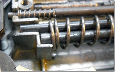
Now how to shoehorn the extremely flexible magazine spring into the recess?
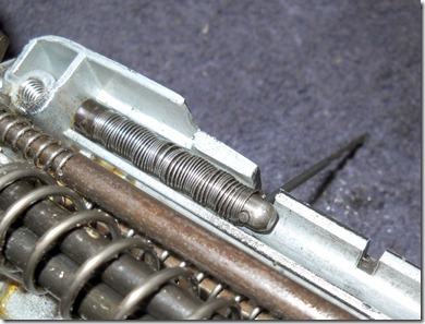
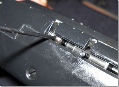
Happily I noticed a small hole drilled in the nose of the rear guide, which allows you to hold the spring back with a small drill bit. There’s a helpful notch cut in the receiver for just such a purpose.
I realigned the spring end so the cut end wasn’t preventing the halves from being reassembled.
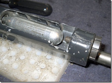
This shows how the drill bit retained the spring. I just pulled out the bit and the spring expanded in place.
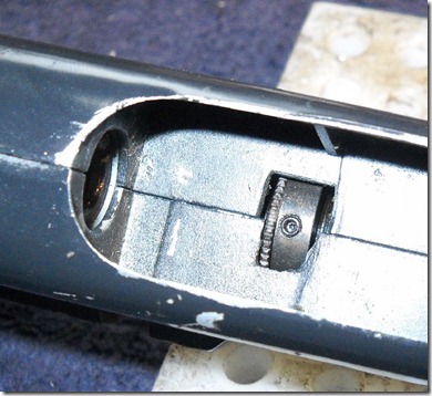
This is what happens when you don’t pay attention…piercing screw was reversed. So I had to disassemble again and flip it around.
Which is good as the exploded drawing says to set the length of the barrel beyond the nut to 17/32”
Presumably further adjustment and locking can be performed from the underside.
The rifle feeds and shoots! But I can hear an extremely small gas leak so I’ll have to tear it apart and make a new exhaust valve seal as well as inspect for any missing parts as the diagram of the valve is somewhat different from what I have.
I was somewhat disappointed to learn that the rifle only cocks to the low power setting with the lever, for full power you have to thumb the hammer back manually after cocking.
The wear on the cam ring means I have to be deliberate when cycling the action, giving the shuttle a little oomph so it will pick up the pellet.
Tuesday, November 9, 2010
Crosman Model 99 Rifle Disassembly, Part 3
On I go…
Two more screws on the left receiver half.
Removed.
The barrel comes free.
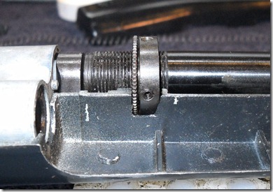
I assume this nut is to adjust the gap between the pellet shuttle and the barrel.
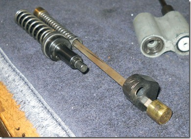
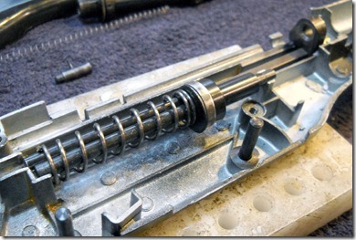
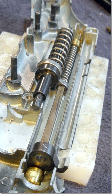
The pellet cam rod, shuttle, etc.
The shuttle does not have a setscrew to lock it on the rod the way the model 600 does.
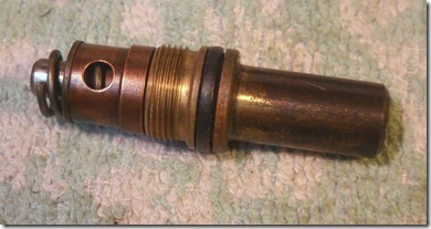
Valve assembly.
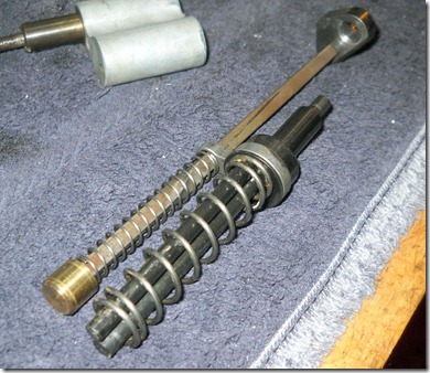
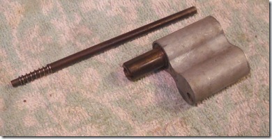
Spring on the end of the valve stem extension/transfer rod.
It slides out of the valve assembly.
Piercing pin nut.
Removed, the mesh filter comes out as well.
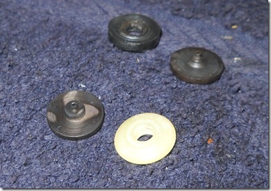
Piercing pin parts.
The seal is a metal ring with a rubber center. Odd. In theory I should be able to use the piercing pin and seal used on the Model 38 pistol, I hope.
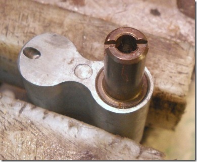
Valve stem housing.
Unscrews…
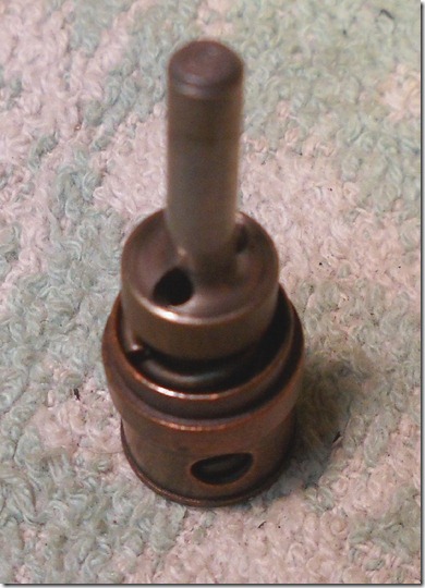
Valve assembly.
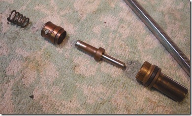
Exploded.
The valve seems to be the same as on the Model 38 revolver.
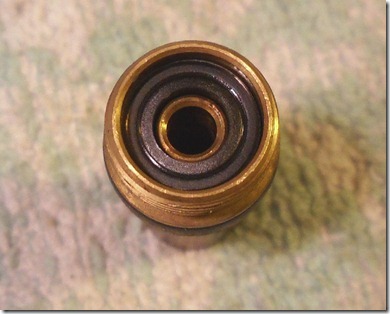
Seal inside the nut.
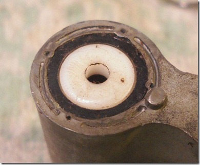
This plastic piece is loose, but retained by a staked steel washer. I’m going to keep it in place, unless forced by circumstances to replace it.
Now to clean and get together some replacement parts & seals.