Friday, March 19, 2010

A New Crosman 22XX--Making a Hammer Part 2

Back to work.

Marked a line to locate the cocking pin hole.

Center drilled,

Drilled undersize

Brought the hole to 1/8" diameter.

And counterbored for the shoulder on the (as yet unmade) cocking pin.

Need to create some breech screw clearance in line with the cocking pin hole.

Started by filing a flat.

Then transferred to the Taig and ground a curve. Protected the ways with some foil to keep abrasive grit at bay. Cleaned the lathe bed thoroughly afterwards.

I'm still on the left.

A larger clearance area than the stock Crosman.

Hardened the face of the hammer. Hopefully correctly.

Polished it out again.

Skipped a step earlier and needed to reduce the OD to approximately 0.738" to achieve a sliding fit inside the gas tube. The front of the hammer laughed at the HSS lathe bit I tried first. A small carbide tipped cutter did the trick. The rear of the hammer is much softer. I was hoping for a differential hardening and it looks like it was achieved. I didn't remove all the machining marks on the body. My thought was the small grooves would hold and retain some lubrication. Blued the part with Birchwood Casey Perma Blue Paste.

Ah--almost forgot. I made the clearance area larger because the hammer was heavier than the Crosman. When finished, it was only 2 grams lighter than stock. Pretty close for winging it.

More parts to come.

Tuesday, March 16, 2010

A New Crosman 22XX--Making a Hammer Part 1

I sort of started this Crosman 22XX pistol build a few weeks ago. There are a few small parts I need to make in order to finish. Among them, the hammer (or striker if your prefer), bolt, bolt handle, cocking pin, breech cap and gas tube endcap. I'm probably forgetting something. I still haven't committed to a caliber. I'll have to decide before I make the bolt.

Figured I'd use a stock Crosman hammer as the model. This is the current hammer, it's got a half-round relief groove to clear the rear breech bolt.

Chopped off a piece of 0.750" diameter drill rod.

OK.

Yep, faced both ends.

Figured I'd start with the bevel on the face of the hammer. Butted the Crosman hammer against the faced end and angled the knife to match the angle. Basically, just used the stock part for my set up. Easy--and no measuring.

Then turned the same bevel into the work piece.

Measured the OAL of the hammer,

and transferred that to the piece. The layout fluid lets me see the line to cut to.

Faced the workpiece down to the line. It's well within 0.001". More precise than it needs to be. It just smacks the valve after all.

Mine is on the left. Need to drill a hole for the hammer spring.

Spotted and drilled successively larger. Finished at 5/16" diameter. Then (not shown) using a 5/16" center cutting end mill, I cut the bottom of the hole flat for the end of the spring.

More layout fluid. Did some measurements and transferred them to the workpiece.

Some comparison with my SPI angle gauges measured the angle at 25 degrees. The angle is cut with the compound crosslide.

Took some time and repeated comparisons to get the length of the tapers to match. Mine is on the left.

Need to cut a relief groove, notch, whatever to clear the breech bolt (It'd actually just be easier to cut the bolt shorter) and the hammer still needs a hole drilled for the cocking pin.

Next time.

Monday, March 15, 2010

An Interesting Muzzle Weight for the HW35

When I bought the HW35E a month or so back, I also found this British made muzzle brake/moderator. Came in a plain cardboard box with a "made in England" sticker. The only other markings were handwritten: "for HW35 2-piece unit adapter and moderator for use with open sights all aluminum-unfinished"

Not much to go on.

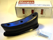
I assumed the end cap was threaded to the main tube. Nope. It was juts a bad press fit. Inside, I found 2 coil springs and an aluminum cone shaped spacer. The piece on the far right is held onto the gun via the front sight and the brake threads into it. Please leave a comment at the end of the blog post if you know who made this thing.

Since the end cap didn't press fit all the way home--and since that's a lousy way to retain a part on a spring piston rifle, I shaved the OD of the cap down in the Taig.

Holding the piece was tricky--as was finding a knife that allowed enough clearance. A tiny homemade boring bar ground from a 1/4" blank tool bit just fit.

Now the cap will press in flush.

The body is marred in several spots. How many years of rattling around in various drawers? I'd think 20 to 25.

A well-greased dead center to hold the free end of the brake and a deft(ha!) touch on the carriage.

Many light passes later removed all the dings.

Another view.

A scotchbrite pad held against the surface gave a nice matte finish.

Did the same to the "adapter" piece.

Again, just another view.

Wasn't thrilled with the brake cap being simply press fit. If I do install the springs, they bear directly on the cap and will force it out of position. With the cap gingerly held in the 3-jaw, I cut a groove almost at the shoulder with a small parting tool.

Yet another view

And added a small, thin o-ring.

Size--unknown. Just grabbed something from a Plano box full of rings that looked somewhat promising.

With the cap pressed in, I marked 3 holes around the circumference.

And drilled with a #43 (0.0890") bit.

Followed up with a #4-40 tap. Did this 3 times.

The setscrews thread right into the outer wall of the brake as well as into the cap. It's not moving.

The brake wiggles a bit when installed on the HW35. I found an M5 x .8mm set screw to modify. Cut one down with a hacksaw and threaded it into an M5 nut--on left. I think the set screw was originally for a Leapers/Centerpoint scope mount as a recoil stop pin.

Faced the set screw.

And using a 3/32" end mill, drilled a flat bottomed hole.

Then turned down a small piece of delrin (AKA: acetal) to fit. Parted it off and pressed it into the set screw. The delrin protrudes about 0.050"--enough to not mar the barrel.

Drilled the bottom of the adapter with a #20 bit.

And using the chuck as a tap holder, tapped the hole to M5 x .8mm for the set screw.

Installed over the ugliest carpet in the attic I could find.

Interesting design. I'm fascinated with how they thought to mill the brake for the front sight. I can't imagine how many models of bases they'd have to make to fit all the various guns. Didn't bother to install the springs or the aluminum cone. There is absolutely no noise reduction whatsoever. Don't yet know if this is a keeper on the gun. The rifle looks like it could be used for pole vaulting, it's so long.