Friday, August 13, 2010

BSF S20 WCM Pistol Disassembly, Part 2

On I go…

08121022

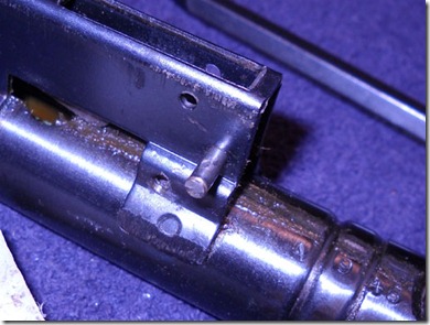
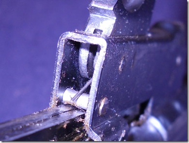
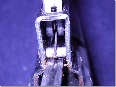
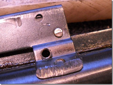
That extremely annoying pin, which the trigger spring rests on, prevents removal of the cocking lever. It is peened on both sides.

08121023

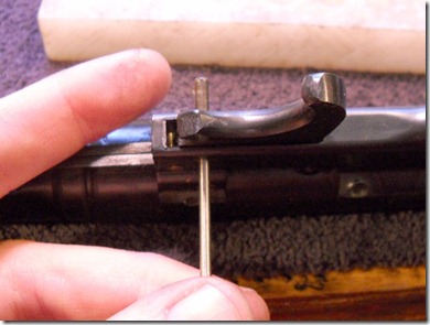
So I carefully filed one end until I could punch it out.

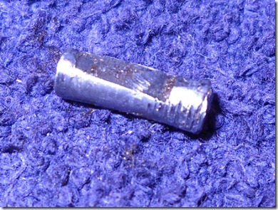
08121032

I’m not sure why there’s a tapered flat on the pin, possibly to clear the cocking lever arm? Did I mention I hate that pin?

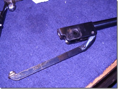
08121024

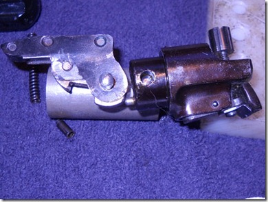
The barrel assembly removed.

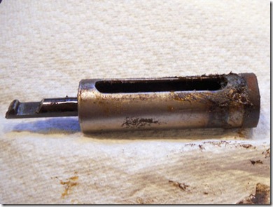
08121025

The piston slid out easily.

08121026

That is not the proper lubrication for a smoothly operating spring piston airgun.

08121027

Piston seal removed.

08121028

The seal is in great shape.

08121029

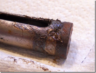
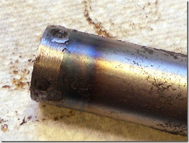
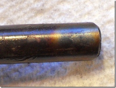
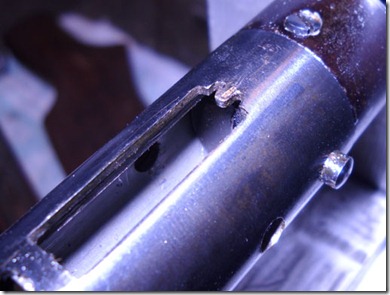
Looks like they welded the end of the piston on and probably tempered it.

08121030

As the other end of the piston sear is likewise oxidized and probably tempered.

08121031

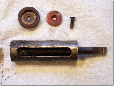
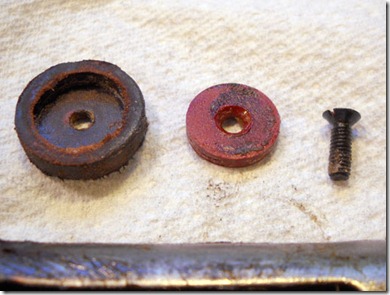
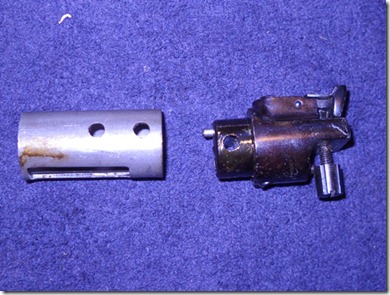
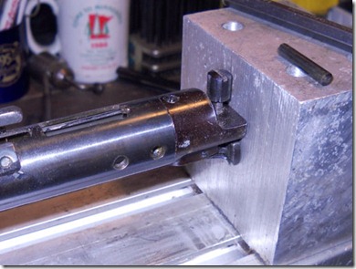
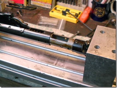
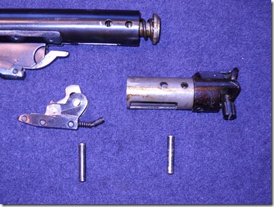
The end plug and spacer.

08121033

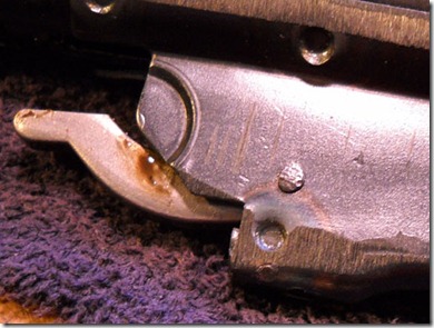
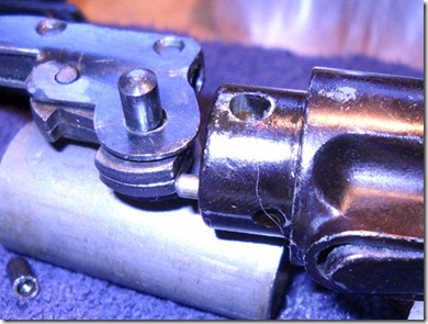
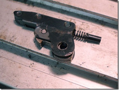
The (for lack of a better word) transfer bar is retained by an extremely peened pin and I decided there was no need to remove it.

08121034

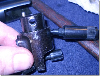
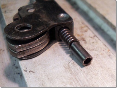
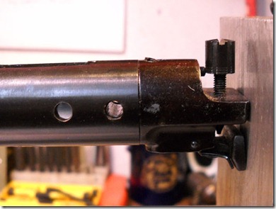
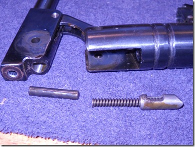
There’s a dowel pin with a round nose that sticks out of the end plug. It sets the amount of sear engagement.

08121035

It bears on the central part of the sear assembly.

08121036

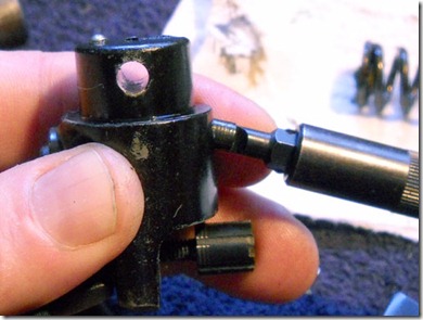
The pin stickout is controlled by a screw in the plug. The pin, logically, sticks out more with the screw screwed in…

08121037

…and less with it screwed out.

08121038

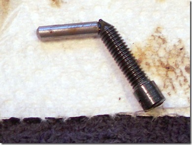
The conical tip of the screw moves the pin laterally.

Now to clean out all the old grease and reassemble.
Thursday, August 12, 2010

BSF S20 WCM Pistol Disassembly, Part 1

As you can probably tell, I’ve been a bit busy lately and have let Derrick do all the work on the blog. I finally had a bit of time and he convinced me I should blog about the disassembly of the BSF S20 WCM pistol he sent me a while back.

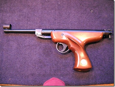
08121001

The pistol.

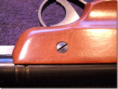
08121002

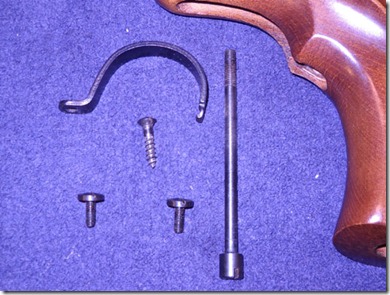
A screw on either side of the stock.

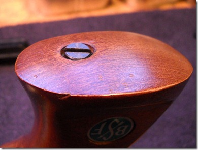
08121003

A screw through the bottom of the grip.

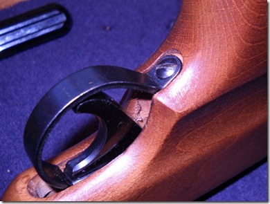
08121004

A wood screw holding in the trigger guard.

08121005

All removed.

08121006

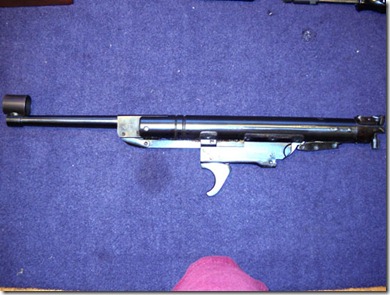
The action.

08121007

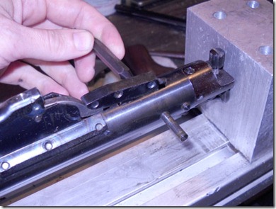
The action held in the spring compressor and the pin retaining the sear is pushed out.

08121008

The sear levers up and out. Notice the relatively strong spring on the right.

08121009

The sear.

08121010

That hole in the end fits…

08121011

…This tang in the tube.

08121012

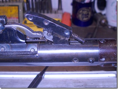
The pin retaining the end plug removed.

08121013

Another view.

08121014

This is the amount of preload on the spring.

08121015

The parts removed.

08121016

Another pin for the barrel pivot. Removing it can allow the detent to fly across the room if you aren’t paying attention…

08121017

Trigger spring bears on what turned out to be an extremely annoying pin.

08121018

Another view.

08121019

Trigger pivot pin pushed out.

08121020

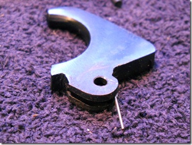
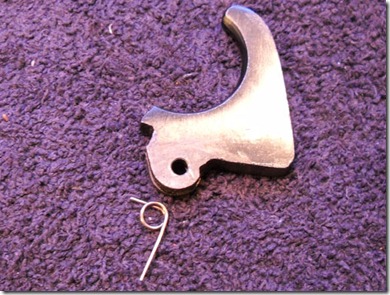
Trigger with spring in place.

08121021

Trigger and spring.

More to come…

Sunday, August 8, 2010

On the Level--Part 2 Final

Moving right along...

Worked this as one solid piece for as long as possible--this made it easier to line up through holes and threads. Drew some guidelines in the layout fluid and spotted a few (three) hole locations. Did my best guestimation of fastener sizes based on available space.

First drilled the center mounting hole with a #36--this is the tapping size for a #6-32. Drilled approx. half an inch deep.

Followed by a #2 bit to slightly recess the head of the bolt. Drilled about 0.125" deep, leaving an angle at the bottom of the hole.
Ground the point off the #2 drill bit and sharpened a cutting edge.
Used the modified bit to counterbore (make a flat bottom) in the hole.

Not shown, a #29 drill bit was used to drill approx. 0.250" deep for the through hole for the #6-32 mounting bolt. Here, I tapped the #6-32 thread to the very bottom of the half inch hole. Confusing, I know. I did as many steps as possible to the single piece. If I'd cut it in half first, I'd have had to do two times as many set-ups--and had alignment issues to consider.

A #43 bit was used on the two smaller holes. Drilled approx 0.250" deep.

Tapped #4-40 to the bottom of the holes.

Mounted the piece in an insert vise and bolted it to the Taig's crosslide. Couldn't get more than a singe bolt to hold the vise down, so I backed it with a steel block anchored into the T-slots. The vise couldn't twist against the backer. The slitting saw was mounted in a homemade arbor.

Slow speed, slow feed. Lots of cutting fluid.

The clearances around the slitting saw were super tight...

but it worked. Sanded the parts down to 400 grit, then cold blued.

A 5-minute epoxy glued the level into the mount.

Installed the #6-32 screw. This provides the majority of the clamping pressure to the dovetail.

The two #4-40 screws installed.

Mounted on a Benelli target pistol.

The #4-40 setscrews still need trimmed flush.

Test fit the level on several different guns. Seems to fit well on all the various .22 dovetails I tried.

As the mounting bolt is tightened, the block wants to hinge upward slightly--like a V. The two setscrews are screwed inward to cantilever the base back down until it's flat.

Very fine adjustments--and clamping security--are possible by varying the pressure between the mounting bolt and the adjustment set screws.