Saturday, April 19, 2008

Disassembling a Crosman 38T

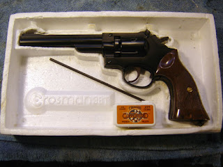
I bought this Crosman 38T in January at the Elk's Gun Show in Albany. I noticed it on a dealer's table with a sign saying "Free Crosman With Daisy", next to a Daisy BB rifle. As I have no interest in BB guns I asked how much it would be if I just bought the Crosman. He said "Make me an offer", so I said $25.00. He told me it would be $20, as I think he thought I was insane for wanting an air pistol.

The 38T was in pretty good shape cosmetically but with as most old CO2 guns (at least the ones I buy), when I inserted a CO2 cartridge gas spewed all over the place. Sigh. I downloaded the .pdf of the exploded drawing from Crosman. This drawing shows how all the components fit together and has instructions for rebuilding the valve.
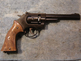
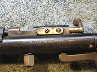
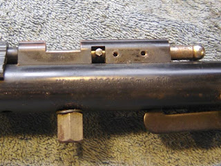
The is the other side. That screw in the middle of the fake cylinder holds the valve body in place.
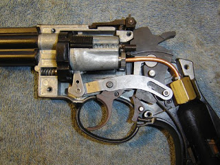
With the side plate removed you can see the mechanism and valve. Notice the small bushing that rides in the slot of the pawl arm. This can fall off if you flip the pistol over, so be careful.
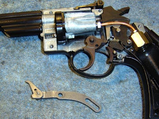
First up was to remove the pawl that rotates the cylinder each time the trigger is pulled.
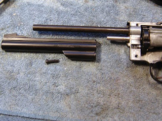
Then the barrel shroud retaining screw was removed with a long screwdriver.
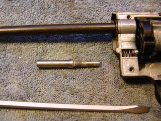
The pin that retains the pellet cylinder was unscrewed.
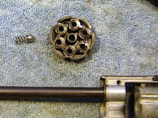
And the cylinder, spring and ball were taken out.
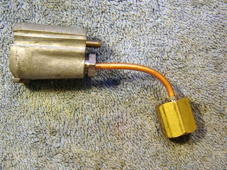
The screw on the back was removed and the valve assembly came free.
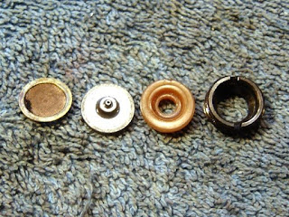
The CO2 cartridge seal parts were removed by unscrewing the black nut on the right. The seal itself seemed scarred up a bit.
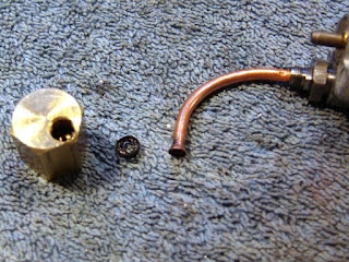
The copper line was pulled free after unscrewing the small gland nut, the seal seemed chewed up, whether by removal or age.
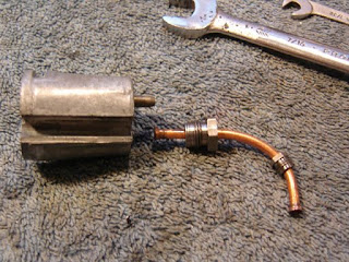
The other gland nut was unscrewed.
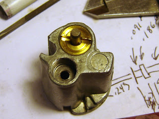
The valve requires a tool that clears the valve pin to unscrew.
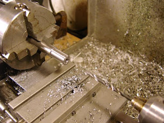
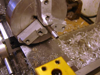
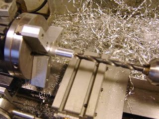
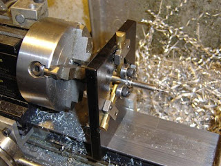
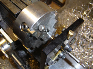
A piece of steel was chucked up, turned to a diameter smaller than the valve nut and drilled to clear the valve pin.
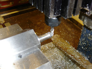
I then milled it to make a screwdriver type blade.
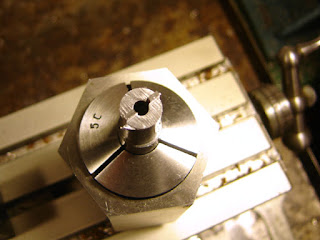
Not a complex tool, and you can just grind a small socket or screwdriver rather than machine a tool.
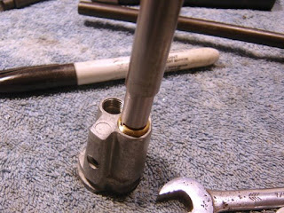
Unscrewing the valve nut.
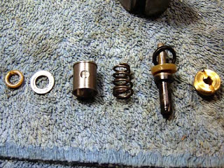
The parts were removed.
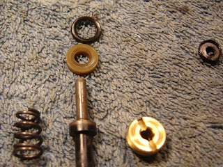
The small black seal on the upper right is for the gas tube where it goes into the valve body. It looks bad but actually wasn't.
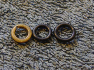
The valve o-ring on the left did have a big nick in it. So I replaced it with a buna o-ring. This is not ideal, and it would be better to use Viton or Urethane, but I figured it would hold long enough to see if the rest of the valve could be sealed.
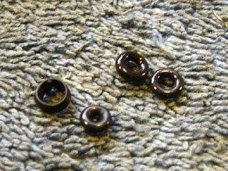
I replaced the small copper tube seal with a viton o-ring. Not ideal either, but I figured it would deform to seal. I was going to use the larger ones on the right, but the small one ended up expanding when placed on the tube to virtually the same OD as the original seal.
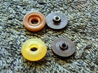
Luckily I had a replacement CO2 piercing pin and seal that came with another 38T I bought from the yellow classifieds. Otherwise I would have to hunt around for parts from the usual suppliers such as Bryan and Associates. Notice the difference between the parts - the new seal is a later design recommended in the .pdf from Crosman.

I was going to make a new seal out of Urethane rod or Teflon, but since I had the replacement part I figured I'd use it and see if the other repairs held. Now of course I'll have to find another leaky CO2 gun just so I can try making a CO2 seal...

Anyway, that's how you take one apart. To put it back together, just go in reverse...
I mostly made this post so I'd have pics should I take another one apart and forget what goes where.

A day later and the pistol has held CO2 overnight, shoots well, and I'm delighted. I now have 3 functioning 38T revolvers, 2 in .177 and one in .22.
Thursday, April 17, 2008

A Rare Sheridan Problem

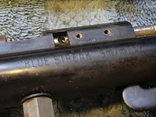
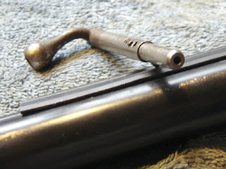
I bought an 1967 era Sheridan at the flea market years ago. I never shot it much as it was missing the rear sight. I recently decided I should fix it up and found it wouldn't shoot. Looking at the bolt I realized that the front part of the bolt, which pushes the pellet into the bore, was missing!

I don't know why I removed the action from the stock, although it take up less space on the bench that way. That plate and the cam beneath needs to be removed.

Which exposes the bolt cam pin. This has a hexagonal section and is unscrewed from the bolt, allowing the bolt to be withdrawn from the action.

The excellent article "Let's Repair a Sheridan Model C", in Airgun Hobby Magazine Volume 4, #1, shows how to make a tool from a 1/4" setscrew. So I made the tool. Basically you turn down the end with the hexagonal socket to clear the slot.

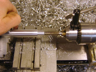
I then tapped a piece of aluminum for a handle and loctited the setscrew in.

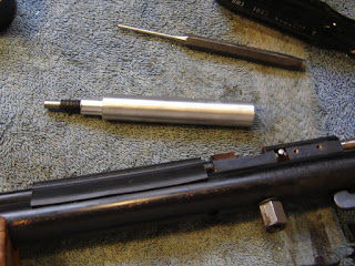
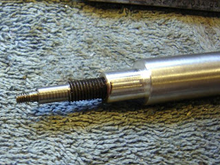
The finished tool.

The pin was unscrewed from the bolt.

Now the bolt can be removed from the action. The article says "Be careful not to lose the bolt spring, which can pop out.", which is exactly the mistake I made, as the action is less akin to a "pop" than to a jet assisted takeoff across the shop. Luckily I had a replacement.

Notice the neat hole in the end. I couldn't find any reference to what I assumed was a two piece bolt (not to be confused with a two piece bolt of the handle and bolt...) so I asked on the AVA forum, which resulted in the information that for a short time Sheridan made two piece bolts:
"The design was a failure, as the pin would sometimes separate from the bolt and either get shot out the barrel or get caught in the exhaust transfer port. A rifle that is missing the pin will not shoot a pellet, as the pellet does not get pushed past the exhaust port when the bolt is closed."

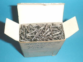
"Kennyboy", who supplied the above information, also has kindly allowed me to use his picture of a box of the loading pins. He's sending me one as well but I figured that it would be best to make my own replacement, since the originals didn't work so well. Having the replacement pin will allow me to keep a bit of obscure Sheridan history, as well as the option to return it to stock configuration should I ever feel the need.

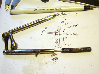
Some measurements were taken from another Sheridan bolt (yes, I have two Sheridans...)

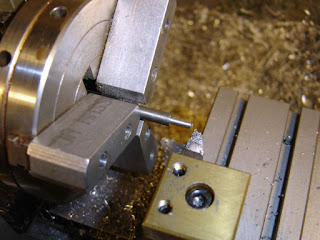
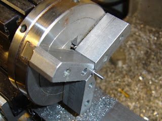
The pin was turned down from 1/4" mild steel.

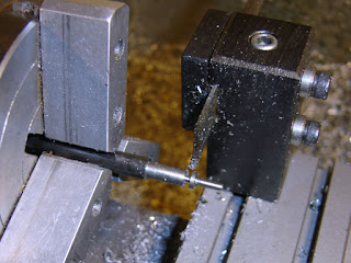
The rest of the pin was cut using a parting tool in steps, past the flange.

Once cut off, I tidied up the other end.

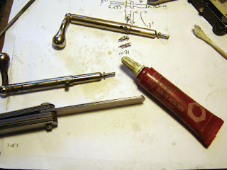
I used Loctite 640 High Strength Sleeve Retainer compound to cement the pin in the bolt. The feeler gage was used to set the gap exactly as on the bolt above. The Loctite has good gap filling capability and high strength, approaching that of steel.
I put on a new o-ring and reassembled the rifle. I shot a few pellets through it with no problems.
Now I just have to wait for Crosman to ship a few rear sight parts, fix a crack in the forearm, and the rifle will be done.

Tuesday, April 15, 2008

Chucking a One Piece Sheridan Bolt in the Lathe

Tom says:
In the case of Sheridans, I've always used the early bolts where the handle was pinned to the bolt body in order to seperate them so I could chuck the body of the bolt into my lathe to do the boring for the new probe. With early bolts now being hard to find if you can figure out how to chuck up the one-piece bolts in a Taig or 6x18 Atlas please share that info with me!

First drill a piece of aluminum to go around the bolt (I used a letter "K" drill), but you should measure the bolt diameter and use a drill just slightly over size.

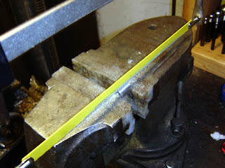
Part it off and slit the it lengthwise. I used a hacksaw but you could use a slitting saw in the mill, or whatever works.

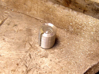
The finished bushing.

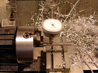
Indicating the bolt in the 4 jaw chuck to run true. This is a bit difficult, so take your time.

Fit the steady rest to support the bolt more rigidly.

You should have plenty of clearance for the handle.
You could use the 3 jaw as well, which would be quicker, not quite as accurate unless you bore the jaws for the diameter of the bushing.

Anyway, that's what I would do...