Some more fun...
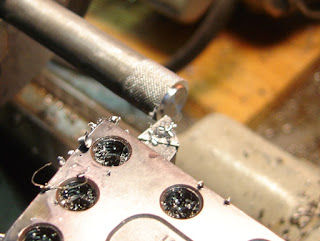
A smaller piece of steel, knurled and turned.
Tapping #8-32. The drawing calls out #8-36 but I'm a rebel. This does have implications down the line...
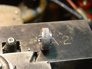
Parted off.
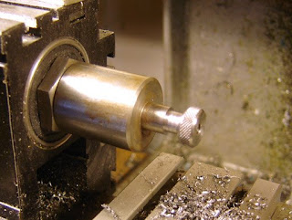
Mounted on a mandrel for facing off.
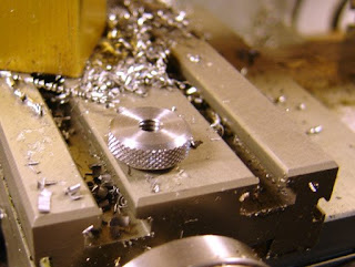
Done!
Now the aperture. Turned to diameter.
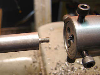
Threaded #8-32
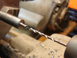
Drilling the major diameter. I reduced it a bit from the drawing to take into account the deeper thread depth of the #8-32 over the #8-36 (A difference of .003" thread depth)
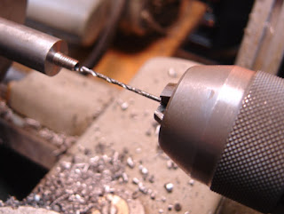
Drilling the aperture hole. I also reduced this, but mainly because I like a smaller aperture.
Knurling.
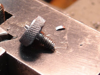
Parted off.
Blurry picture of boring out the face.
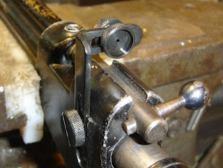
Blued with Oxpho blue and mounted on the rifle. Works fine. It's a fun and accurate rifle to shoot.
Friday, May 1, 2009
Thursday, April 30, 2009
Fabricating a Replacement Sight for a Crosman 101, Part 2
On I go.
Knurling some steel.
Turning down to one diameter.
Then to the screw diameter, and threaded with a die.
Undercutting the thread. I probably didn't need to do this but it's on the drawing...
Parted off.
Mounted on a mandrel and the end faced and chamfered.
Slotting a screw slot.
The drawing shows that it's a plunge in from center rather than a straight cut. Not that it matters.
The finished screw.
It mounts the sight bracket to the rifle.
Wednesday, April 29, 2009
Fabricating a Replacement Sight for a Crosman 101, Part 1
As I mentioned before, I have three Crosman 101s. One worked fine and had been resealed by the previous owner but was missing the rear sight. So armed with D.T. Fletcher's parts drawings CD I decided to fab up a replacement. Unfortunately the drawing for the later model bracket was not supplied so I had to extrapolate from the early drawing and some pictures. This led to a slight mistake...
A piece of steel covered in layout blue was propped against my Taft Pierce box parallel, on my surface plate.
Scribing some lines...
Lines all scribed to my drawing.
I marked the parts to be removed (little x's) and scribed some radii.
Cut out most of the waste on the bandsaw.
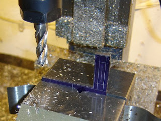
Milling to the lines.
Needed a tall endmill...
Milling the slots.
The radii were ground on my belt grinder.
I thought my Di-Acro bender would handle the job...
But I ran out of bend...
So I had to finish the 90 degree bend by hammering in a vise.
The bracket. This is where I made my mistake. The bend should have been 90 the other way. On the old bracket the bend (not really a bend as the whole thing is stamped to shape) is this way, but not on the newer one...shouldn't matter much functionally but it is wrong.
Mounted to the rifle.
Polished and deburred.
Subscribe to:
Posts (Atom)