On I go…
I removed the CO2 clamp & screw.
One screw on the other receiver half.
Notice how corroded the screw is…
This freed up the valve assembly. One spring was unhooked.
The valve assembly with barrel and magazine attached.
It’s important to take pictures of how spring hooks are oriented.
Everything is rusty.
The trigger group.
It’s somewhat interesting and different.
This piece pivots on that pin.
Let’s take more pictures. It will help.
You know it hasn’t been shot when it has cobwebs.
The grease has dried out completely.
I punched out the one, longer, pin.
Interesting spacers.
I tried to remove the shorter pin but it seems swaged – best to leave it. I can clean around it.
More to come…
Friday, September 9, 2011
Crosman Powermatic 500 Disassembly, Part 2
Thursday, September 8, 2011
Crosman Powermatic 500 Disassembly, Part 1
Having hit a velocity wall with the V-350 I decided that a slight change of pace was in order. So I dug a Crosman Powermatic 500 out of my pile of airguns.
Not a bad looking rifle, with the same lines as most other Crosman air rifles of the era.
It has an inline BB magazine above the barrel.
There’s a bit of corrosion.
Power Matic 500
More corrosion. This isn’t inspiring confidence.
This is where the CO2 cartridge goes, The plastic plate which hides it is missing.
As is one forestock screw.
Time to begin by removing the buttstock.
The stock is really heavy. I believe that this is a Croswood stock.
Removing the one remaining forearm screw.
The knurled CO2 nut needs to come off.
I clamped the nut in the vise to get the punch started on the roll pin and then removed it so I could rotate it 90 degrees to fully tap it out.
Notice that the forearm isn’t lightweight like a plastic part – it only has enough material removed for the parts to fit in.
The “barrel” band holds the shoud to the stock.
I removed three screws.
And carefully separated the halves. Nothing shot across the room, which is always a good thing.
As you can see the innards are corroded and full of cobwebs.
I took a bunch of views to make reassembly easier.
Notice that the safety is missing.
Another view…
Not really that complex although I’m unsure how the mechanism works.
More to come…
Tuesday, September 6, 2011
Tech Force TF79 / AR2078A Upgrades--Part 9
Some quick notes about what's coming in the semi-near future: I've got one of Frank B's Feinwerkbau 124Ds to overhaul with some Maccari parts--and I may use that as an excuse to take a break from the Tech Force. Also, I have a lost post from August of 2009 that I started to write, then shelved, on a stock modification for a BAM B26-2. I liked the concept, but I wasn't happy with my sketches or the first prototype. (We call them prototypes when it all goes wrong) Anyway, I've got a better(?) way this time around, so that's back towards the top of the project que.
Right now, I'm checking back in with our slowest airgun project to date: The TF79.
With the holes drilled for the adjustable cheek piece, it was necessary to add two more additional holes in the side. I'll make threaded aluminum inserts for these holes that will house screws to lock the cheek piece in position.
 Yeah, there was layout to find the locations for the holes. The 1/2" holes allow for easy insert manufacture from a piece of stock aluminum rod.

 Many chemical strippers have a shelf life and my old can of Strypeeze was apparently done. It barely softened the finish.
 Got a can of Dad's Easy Spray and it did the trick on the heavy Tech Force finish. I'm guessing that it was an acrylic. Whatever it was, it was excruciatingly difficult to remove. Sanding it all off was out of the question due to it's thickness as it instantly loaded the sandpaper.
 Some thin stain left behind. That was straightforward to sand out. Sanding drums, the Dremel tool and a lot of time reshaped and blended the adjustable cheek piece into the body of the stock.

 Here it is, sitting at 100 grit. Needs to go to about 220 or so to be somewhat respectable. There's a few tiny areas that still need the factory stain sanded off. Probably another two hours of work before it's ready for some color.
 Happily surprised to find zero wood filler. From all the airgun article I've read over the years, I was led to believe that massive amounts of wood putty was mandatory for China made rifle stocks. Maybe in the past, maybe on some, but not here. The only filler present is the small amounts of epoxy that I added when fitting the slot for the accessory rail.
 I'm tempted to make a slightly flared maple grip cap to get some extra length on the short (for me) grip. Since it's taken this long already, I'll probably do it.
 Assuming that the dark areas are mineral streaks. I've no idea what kind of wood this is. Hope it stains well. Let me rephrase that. I hope it stains well the first time, as I have no desire to sand it out and start anew.
More soon.
Assuming that the dark areas are mineral streaks. I've no idea what kind of wood this is. Hope it stains well. Let me rephrase that. I hope it stains well the first time, as I have no desire to sand it out and start anew.
More soon.
 Yeah, there was layout to find the locations for the holes. The 1/2" holes allow for easy insert manufacture from a piece of stock aluminum rod.


 I'm tempted to make a slightly flared maple grip cap to get some extra length on the short (for me) grip. Since it's taken this long already, I'll probably do it.
 Assuming that the dark areas are mineral streaks. I've no idea what kind of wood this is. Hope it stains well. Let me rephrase that. I hope it stains well the first time, as I have no desire to sand it out and start anew.
More soon.
Assuming that the dark areas are mineral streaks. I've no idea what kind of wood this is. Hope it stains well. Let me rephrase that. I hope it stains well the first time, as I have no desire to sand it out and start anew.
More soon.
Tuesday, August 30, 2011
Tech Force TF79 / AR2078A Upgrade--Part 8 Adjustable Cheek Piece
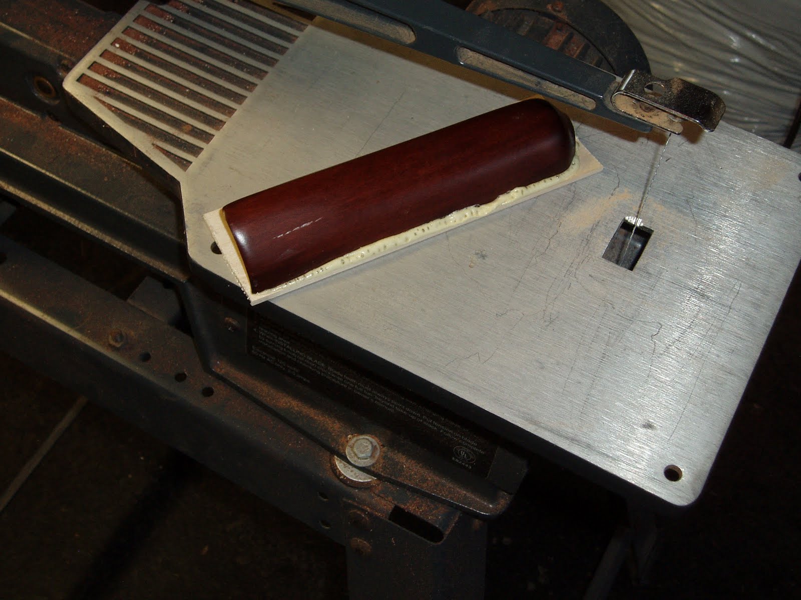
With the adjustable butt plate ready for installation, I went back to the stock for an additional change. Wanted to make a relatively simple adjustable cheek piece. Didn't have a bandsaw available and didn't want to bother anyone for a single cut. What's the worst that can happen?
 Taped up the stock and just made the cut with a scroll saw.
 Had to do only a minor amount of truing up the cut surfaces. Just to make things even easier, the rear of the piece was cut at an angle.
 With the thickness of the saw blade as well as the clean up on each piece, there was a gap.
 Found a piece of maple and the Gorilla Glue...
 and clamped it up.
 Trimmed the maple back a bit.
 Glued up a second piece of maple to the angled rear cut.
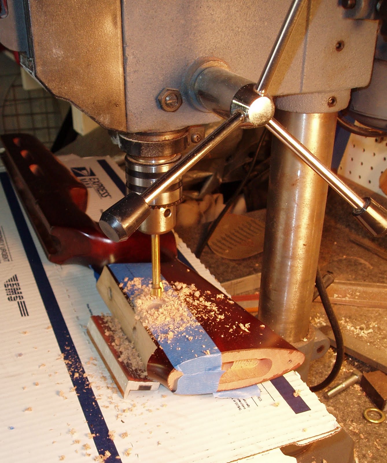
 In a huge fit of stupidity, I elected to use blind holes for the adjustment rods in the stock and cheek piece. Had I any sense, I'd have drilled from the bottom of the stock upward into the cheek piece before cutting it off. That would have aligned all the holes--but left two visible holes in the bottom of the butt stock. Blind holes require drilling four holes in two pieces and get all of them correctly aligned. As I'm working on this in my free time, it took a couple days to work out how to make this happen. After marking the butt stock, I center-punched the marks. Set a 1/8" ball bearing into each marked hole. Aligned the cheek piece and seated it firmly into the stock. The two ball bearings transferred small dimples to the cheek piece to mark the hole locations.
 Used a bubble level to align the bottom edge of the cheek piece.
 Drilled the holes with a 1/2" forstner bit. These are the holes in the cheek piece that the adjustment rods will be glued into. I didn't get any pics while drilling the butt stock. My fixture was too horrific for pictures. Essentially, I leveled the flat section in a similar manner to the above pic and drilled the holes. Uh, essentially.
 Cut off a couple pieces of 0.500" aluminum rod.
 Faced then beveled the butt stock ends
 The cheek piece ends were test fitted, marked for seating depth, then grooved for the eventual glue that will hold them in place.
It took an evening, but a test fitting proves the cheek piece holes all line up and it slides up and down. Need to make a couple fittings to hold the cheek piece in place, then refinish the stock.
Astonishing sidebar: This is the 550th posting for the blog. Congrats, Nick.
As always, more soon.
The cheek piece ends were test fitted, marked for seating depth, then grooved for the eventual glue that will hold them in place.
It took an evening, but a test fitting proves the cheek piece holes all line up and it slides up and down. Need to make a couple fittings to hold the cheek piece in place, then refinish the stock.
Astonishing sidebar: This is the 550th posting for the blog. Congrats, Nick.
As always, more soon.
 Taped up the stock and just made the cut with a scroll saw.
 Had to do only a minor amount of truing up the cut surfaces. Just to make things even easier, the rear of the piece was cut at an angle.
 With the thickness of the saw blade as well as the clean up on each piece, there was a gap.
 Found a piece of maple and the Gorilla Glue...
 and clamped it up.
 Trimmed the maple back a bit.
 Glued up a second piece of maple to the angled rear cut.
 In a huge fit of stupidity, I elected to use blind holes for the adjustment rods in the stock and cheek piece. Had I any sense, I'd have drilled from the bottom of the stock upward into the cheek piece before cutting it off. That would have aligned all the holes--but left two visible holes in the bottom of the butt stock. Blind holes require drilling four holes in two pieces and get all of them correctly aligned. As I'm working on this in my free time, it took a couple days to work out how to make this happen. After marking the butt stock, I center-punched the marks. Set a 1/8" ball bearing into each marked hole. Aligned the cheek piece and seated it firmly into the stock. The two ball bearings transferred small dimples to the cheek piece to mark the hole locations.
 Used a bubble level to align the bottom edge of the cheek piece.
 Drilled the holes with a 1/2" forstner bit. These are the holes in the cheek piece that the adjustment rods will be glued into. I didn't get any pics while drilling the butt stock. My fixture was too horrific for pictures. Essentially, I leveled the flat section in a similar manner to the above pic and drilled the holes. Uh, essentially.
 Cut off a couple pieces of 0.500" aluminum rod.
 Faced then beveled the butt stock ends
 The cheek piece ends were test fitted, marked for seating depth, then grooved for the eventual glue that will hold them in place.
It took an evening, but a test fitting proves the cheek piece holes all line up and it slides up and down. Need to make a couple fittings to hold the cheek piece in place, then refinish the stock.
Astonishing sidebar: This is the 550th posting for the blog. Congrats, Nick.
As always, more soon.
The cheek piece ends were test fitted, marked for seating depth, then grooved for the eventual glue that will hold them in place.
It took an evening, but a test fitting proves the cheek piece holes all line up and it slides up and down. Need to make a couple fittings to hold the cheek piece in place, then refinish the stock.
Astonishing sidebar: This is the 550th posting for the blog. Congrats, Nick.
As always, more soon.
Subscribe to:
Posts (Atom)
