Friday, April 25, 2008

The 1377 Project: Pump Arm Pin and Retainer

Several people on the Crosman forum suggested that I tie the pump tube plug to the tube with two screws. This makes sense as all that retained it was a press fit 3/16" roll pin, which doubles as the pivot for the pump arm. Roll pins don't make particularly good axles, so I thought about a way of using a dowel pin, and retaining it, while tying the whole thing together mechanically.
This is what I came up with:

I had some 3/8" hexagonal brass which seemed like the right material for the retainer screws.

After turning down to 1/4", I cut a relief groove.

I then reamed it .001" over 3/16"

I used the die holder to make 1/4"-28 threads.

And parted it off the bar.

Two retaining screws.

This is what the assembly looks like.

Drilling the pivot hole in the tube out to 1/4" with a Unibit.

A Cogsdill Burr-Off tool, also known as a "clothes pin" tool.

The tool cuts both back and front and springs to fit into holes. It is very handy for deburring the inside of tubes. As you push it in it deburrs the outside of the hole, and as you withdraw it, the inside.

I drilled and tapped the pump arm plug 1/4"-28.

The finished retaining screws installed. I'll polish them up, although I'm not entirely convinced this will be the final design.

My main aesthetic criticism is that the screw stands proud of the tube, only making contact along the tangent. So I may make two slightly longer ones and make washers with a radius to match the pump tube on one side. This would be stronger, and look a bit better. However it will add width to the assembly and I'm not sure if that will look good either...
We'll see.

Thursday, April 24, 2008

A Month of Blogging

I have to say I'm pleased with myself for the rate at which I have been working on, and posting about my projects here. 9 posts in the past two weeks is pretty good. This is proving to be a great motivator for getting me out in the shop.

It seems I have a growing readership as well, which means I must be doing something right!

I have a bunch of other projects lined up for the coming days, some minor work on the 1377, some adventures and failure in working on the Predom piston seal, and a somewhat crude sight base for the Crosman 187...I have a long list of potential projects in the works as well.

That said, I am always looking for cheap/free project airguns. If you have something taking up space that you never shoot, is too ugly, or can't be repaired, let me know. I need more projects! I have yet to have anyone offer me anything from this periodic begging, but I'll keep it up.

Here's a YouTube animation of a Front Sight design I'm working on...I need to get it all figured out as it will be a bit more finicky than some of the parts I make.

Wednesday, April 23, 2008

Nygord's Trigger Modification of the Daisy 717

The Daisy 717 Match air pistol was the first airgun I ever owned. I bought it in 1982 (I was in high school) when it was offered with a membership in the NRA, for $40 or so. It still shoots well although I had to rebuild it and replace seals, etc. A couple of months ago George, who is a master machinist (check out these pictures of his rifle), gave me his old 717, as he never shoots it and it had stopped working. I rebuilt the valve, which included remachining the valve as they have changed the seat design, and I got it working again. The Daisy is a fairly easy pistol to work on, and should you need to replace seals and such, there is an excellent guide up on the pilkguns site. You can contact Daisy for a .pdf drawing and price sheet for all the parts you need.

I decided it would be a good candidate for a modification I had been wanting to try, the late Don Nygord's adjustable sear. You can download a .pdf reprint of his article here. The article is maddeningly vague and as I mention below, shows far more meat on the sear than actually is there.

Let me say that it's not a good idea to mess with triggers, sears and such. You can't afford to have a gun go off while cocking or charging. Don't do this modification!

The Daisy is a relatively safe design as you first cock the gun then charge it with air, so if the trigger is set too lightly it should go off before charging. Even so, I tested it for accidental discharge by knocking and slapping it around before even thinking about testing it with a pellet. I make sure the gun is always pointed in a safe direction, wear glasses and a bulletproof vest (ok, maybe not the vest).

I won't be held responsible if you put your damn eye out (or more likely, shoot a hole in your foot)! I am not in any way advising you to make these mods. Don't do this modification!
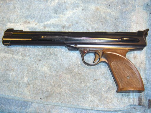

The 717

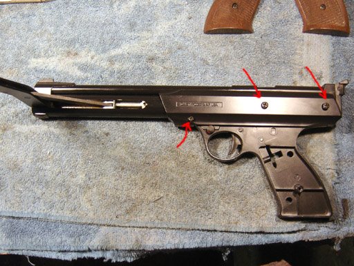
I removed the grips, opened the pump arm and removed the three screws that hold the pistol together.

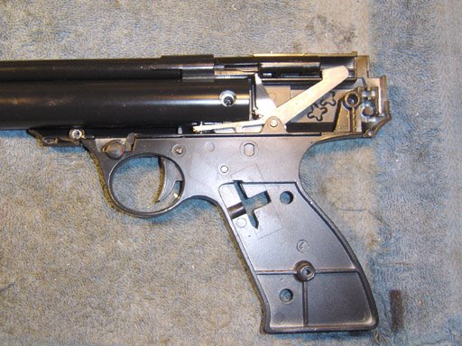
I removed the side plate.

And I pulled off the grip frame and trigger assembly.

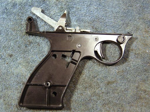
Here's a pic of the other side, mostly for my own reference.

I removed the safety and made sure that the detent ball and spring did not shoot across the shop. There's a first time for everything.

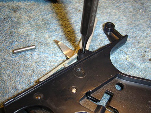
The first of two pins are pushed out. They are a slip fit and didn't require any force.

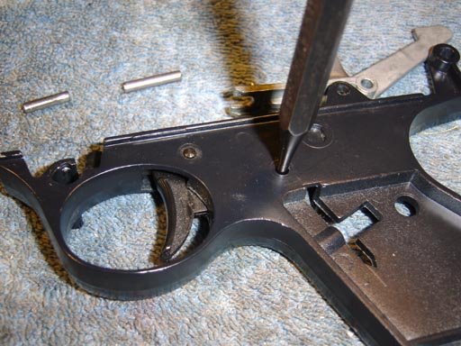
I pushed out the second pin.
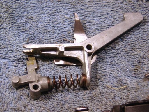
The sear assembly.

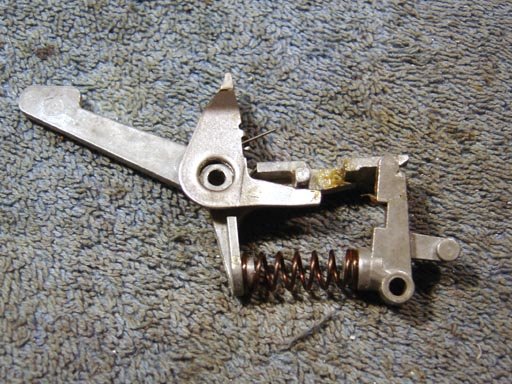
The other side, again for my reference...

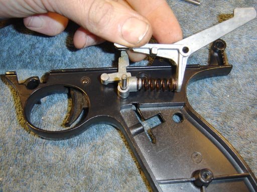
I placed a longer dowel pin in the hole and put the sear assembly on top.

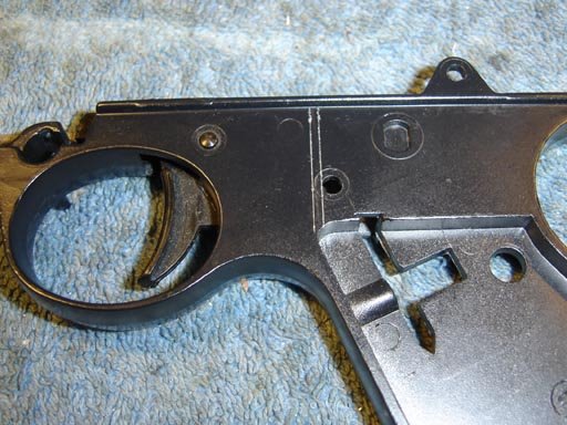
So I could scribe a few lines to determine where to drill the hole. The left line was extended across the top of the frame with a square. I wonder what those cutouts and that boss is for?

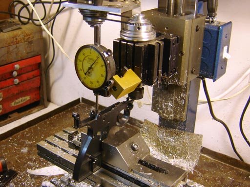
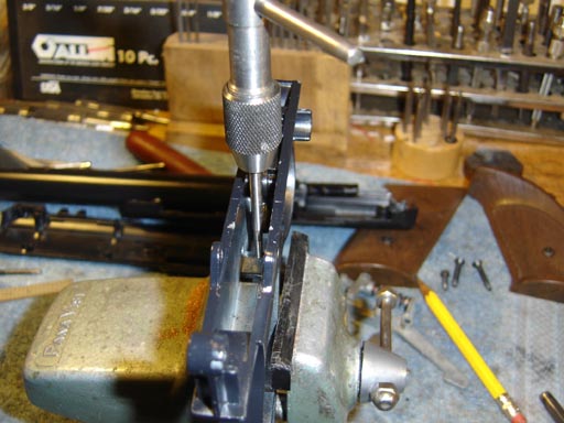
I mounted the frame in the vise and used a dial indicator to make sure it was level.

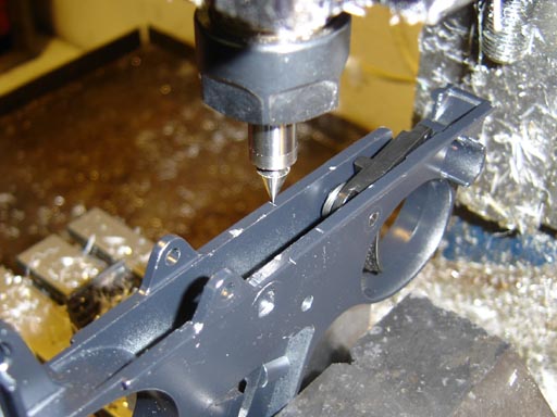
I used a pointed centerfinder to optically (as in I looked at it and lined it up) find the line.

I used an edge finder to find the center of the frame.

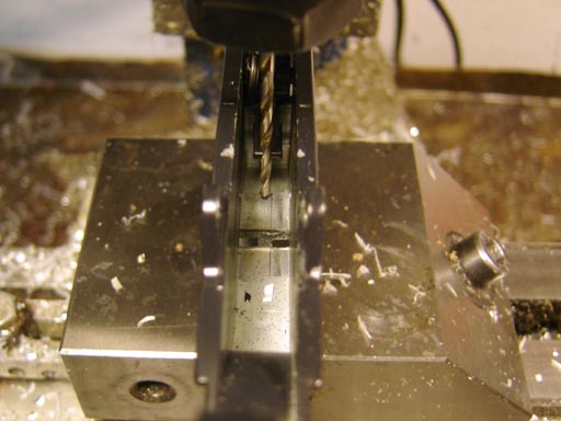
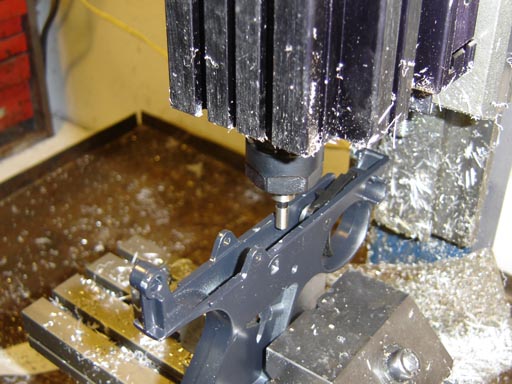
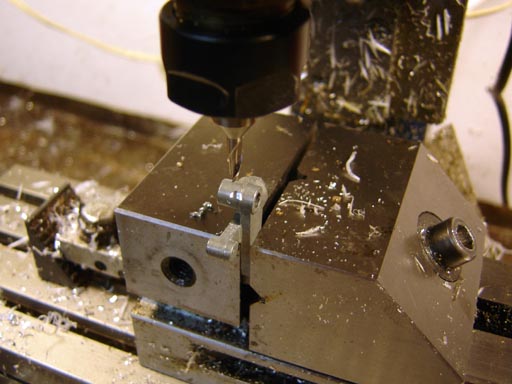
And I drilled a hole for tapping a #4-40 screw thread. Nygord used a #5, but I only had #4 and #6 setscrews on hand.

It looks off center because of the grip molding line, but it's actually perfectly centered.
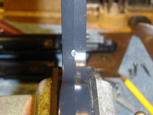
A nice hole.

I then tapped the hole by hand. It's a bit deep and I had to follow up the gun tap with a bottoming tap.

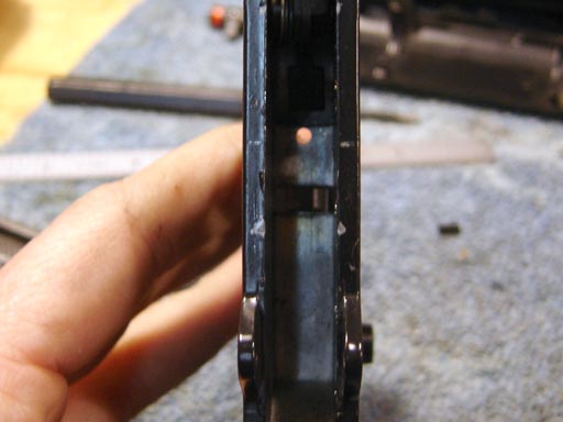
I then milled a seat for the screw on the sear. Nygord's drawing shows a much larger casting boss, which I find interesting. Perhaps Daisy changed the design to prevent this modification? Anyway since I used a smaller screw at least half the diameter of the screw will make contact with the seat.

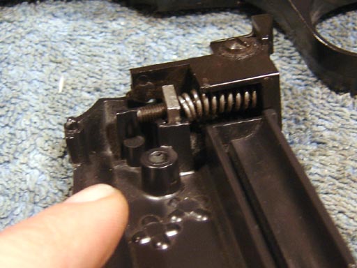
At this point I reassembled the pistol. It wouldn't go back together...I then remembered that while you can take it apart without removing the sight, you have to remove the sight to reassemble as the spring will push out and get in the way when the plate is removed...

I then screwed in a 1/2" long #4-40 setscrew, checking the action each 1/8 of a turn. It is very easy to go from a light trigger pull to the gun refusing to cock at all, so I played it safe and went about 1/16th of a turn when it got close. The trigger pull is noticeably lighter now, I did a blind test with my wife to see if she could determine which 717 had been modified. She selected this pistol as the one with the lighter pull.

Was it worth it? Hard to say. The trigger pull isn't that bad once the gun has been worn in. But I thought I'd try it out. I still can't shoot as accurately as the pistol is capable of anyway.

Monday, April 21, 2008

My New Spring Compressor

I made a spring compressor back when I first started airgunning. It was made of chunks of wood and a pipe clamp. It worked fine. Several years ago, during a new-child-related non-airgunning phase, I got tired of tripping over it and dismantled it. When I got bitten by the airgun bug again, I looked for the parts but I couldn't find them (no surprise for anyone that's been to our place).
A compressor is really needed for serious work on spring piston air rifles, so I gathered a bunch of parts and set to work.

The base is a length of 80/20 type aluminum t-slot extrusion. Angle iron, aluminum chunks, plastic chunks, a knob and some 1/2"-10 acme threaded rod. Notice the acme tap. I bought it years ago for just such a project. I had a bunch of 80/20 tee nuts and other hardware that I have bought over the years from our local scrap yard, plus all the usual nuts and screws I have on hand.

Laying out the mounting holes for the angle iron.

This is very exciting, isn't it. The main reason I procrastinated so long is the tedium of laying out and drilling holes.

I used a letter "Y" bit for the acme tap, seemed about right. I wanted a tradeoff between ease of tapping and strength.

This is a "tandem" style tap, which first roughs in the threads and then the 2nd part of the tap finishes them. I could have probably used 1/2"-13 threaded rod but I figured there was no point in hoarding the acme rod...I still have 3' of it.

Well, it threads in and squarely!

This old fixture knob was drilled out and tapped for two setscrews at 90 deg. Should be strong enough, although I may upgrade to a ball crank to speed things up...

Drilling the holes for the pusher block.

Counterboring for #10 screws, which were used because they were the longest socket head cap screws I had on hand.

The steel strips were transfer punched, drilled and tapped.

It all lines up!

The acme rod was turned down at the end to 3/8" and a small pip intentionally put on the end of the rod...

...So I could transfer the hole location

Pressing in a bronze bearing.

The rod was center drilled on the end to make a vee shaped countersink and the ball bearing inserted between the rod and the block as a crude thrust bearing.
All assembled! It slides smoothly with little play. I may make a retainer of some sort so it also moves the block backwards, right now I have to push the block back by hand to retract it.

Transferring the mounting holes to a piece of thick aluminum angle. It should be plenty strong.

Milling out a slot slightly wider than the barrel diameter of the largest barrel of the air rifles I own. It can always be enlarged should I need to.

For different barrel diameters I will have thick aluminum shims which will closely fit the barrel and allow the maximum surface contact with the breech block face. If the barrel/breech is removed before compressing, this is not an issue, but it seems that sometimes you may want to leave the barrel on the rifle when working on the spring, depending on circumstances. In the past I have worked on all of my rifles with the barrel removed though.

Flycutting two coarsely sawn blocks of UHMW plastic. Both the plastic and the chuck of aluminum for the pusher block were acquired when my friend Kent and I cleaned out a machine shop that was closing. We salvaged tons of scrap cutoffs, all labelled with alloy or type.

One block was set at a 45 degree angle and a vee was milled.

Both blocks were drilled through and sections of 1/4"-20 threaded rod pass through into tee nuts. This is quite secure, at first I thought I would do two sets of these clamping blocks but one seems fine for now.

The spring compressor is finished! I have the back jaws of both bench vises coplanar, which is handy for holding long fixtures and tools of this type. The compressor should be big enough to work on any spring piston air rifle I have or will come across in the future. I have it in mind to make other attachments for this extrusion, such as a rifle vise, or checkering jig, but I'll wait until need arises.