Almost home free. I eyeballed the valve and connector tube length against the gas tube and broke out the hack saw.

I made the cut approximately 3/16" too long for some wiggle room while fitting.

Taped the end of the tube to protect it from the jaws.

Broke out the steady rest. Taped the tube under the fingers. Some grease was also helpful to prevent marking up the blued tube.

Gradually shaved the tube down test fitting the valve assembly as I went. It was done when the valve screw was centered in its hole.

The chopped gas tube.

Want to better anchor the valve in the gas tube. The single screw won't support the weight of the A/S cartridge and adapter assembly.

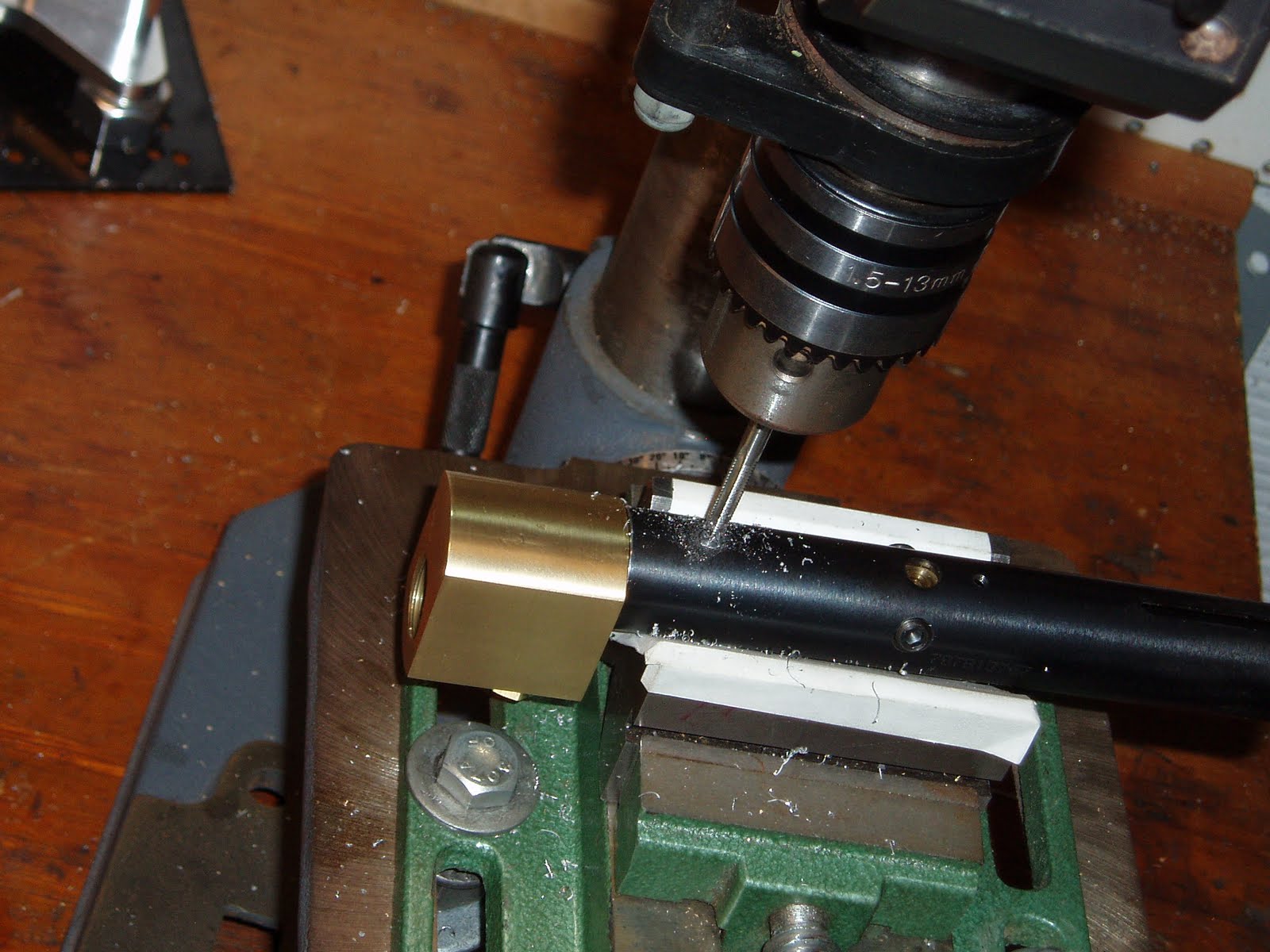
Drilled out the #6-40 valve securement threads with a #29 bit and rethreaded the hole to #8-32. Turned the the head of an #8-32 button head down until it was a very snug fit in the hole. Still want to add two additional valve screws.

Taped the vee block to protect the tube. The tape on the tube itself is for alignment of the additional holes. I spotted the gas tube with the valve inside.

Opened the holes to 0.250"

Removed the valve and deburred both the inside and outside of the gas tube holes with a single pass of a special tool Nick sent me.

It's from Deburr Master. Their
web site shows it in action far better than I could ever explain.

With the valve already spotted, I drilled and tapped the two additional holes #8-32. Not shown: reinstalled the valve into the gas tube, centered up in the vee block and used an end mill to cut a small counterbore at the top of those two additional threaded holes.

Turned down the heads on a couple #8-32 socket head cap screws to 0.250" The heads will bottom in the counterbored holes in the valve leaving the heads protruding through the entire wall thickness of the gas tube. This is one of the best ways to secure the valve as it loads the fastener heads and not the smaller diameter threaded shafts of the bolts. Walter Glover is recognized for coming up with this method of valve securement. I pay attention anytime he posts on the various airgun forums. He knows what he's talking about and his advice will keep you safe.

One of the modified cap screws is on top--the buttonhead is below. I used the buttonhead on the bottom because the grip frame attaches over the screw and requires minimal protrusion.

Since I've taken it this far, I added a vent hole on the adapter. Makes it easier to remove the AirSource cartridge if it's not empty. Just spotted the hole here.

And drilled with a #45 or #46. I didn't really look at the bit. All that matters is that it vents.

Couple more things: I drilled through the gas tube--continuing the thread for the front screw holding the grip frame.

Picked up the thread, then tapped into the connecting tube inside (another #8-32). Careful to not drill completely through the wall of the connector.

Since we're using the drill press, I spotted a hole on top. (This will be underneath the breech)

Followed with the #29 drill bit.

Tapped one more hole to #8-32.

Filed down a set screw so it bottoms in the tube connector and sits flush with the OD of the gas tube.
Uh, I think it's done. So, I guess I'll just put it all together.

Here's a box stock Crosman 2240.

A/S adapter installed with a longer barrel. Probably install a red dot for sighting.

Bleed holes and burst disk.

After bluing the additional valve screws, they don't stand out too badly.

I'll get an addendum up in the future with velocity and shot count.
Absolutely, positively, no idea what's up next. But first, I need a couple days to do some shooting.