Tuesday, May 5, 2009

Derrick's Crosman 180 Repair Part 1

One of my customers, James, came in last week and gave me an old rifle: a .22 caliber Crosman 180 CO2 gun. He said it worked just fine the last time he'd shot it--back in 1978! He remembered the burglary I went through last year and wanted to help rebuild my airgun collection.

The gun is in exceptional cosmetic condition. The bluing is about 90+% I think we figured the gun was from around 1962--mainly by dating the second variant trigger as well as James' recollection.

The Crosman 180 is essentially a shorter and lighter version of the 160. The 160 rifle uses two 12gm CO2 cartridges, the 180 gets by with just one.

A generous amount of Crosman Pellgun oil and about $5.00 in CO2 cartridges proved that the gun leaked like a true champ.

Disassembly time.

Remove the CO2 end cap, the safety and the nut/washer from the locating stud.

Action lifts right out of the stock.

Remove the trigger housing bolts.

A threaded bushing comes out next.

Remove the rear breech bolt.

The hammer assembly slides out. Note the mushroom shaped breech cap.

The hammer plug slides right out.

Inside the rear of the breech, the bolt handle is held in by a screw. Loosen it a couple turns and the bolt handle pulls right out.

Just for the record, this is not the stock bolt handle. I turned this one on the lathe to replace the damaged original. The ball end was gone from the original handle. Initially I was going to make an exact copy, but then decided to add some heft.

Loosen the barrel band and it slides forward off the gas tube.

Remove the front breech screw.

The barrel, spacer, breech seal and gas tube can now be separated.

From the front end of the gas tube, the face of the valve is slotted for a special tool.

I made this from a piece of 3/4" diameter tool steel. A similar tool is currently available from Bryan and Associates. It's their tool #T-9 "valve body disassembly tool".

This is out of sequence, but it shows how the tool fits into the end of the valve face. Here's the important stuff: The valve is made of 2 pieces of brass threaded together at the o-ring. In the gun, the rear of the valve is held fast by the locating stud. The valve tool is then used to tighten the front of the valve--this expands the o-ring outward sealing off the gas tube. In the older Crosman CO2 guns, the valve does NOT seal on the end of the 12 gram cartridge. Because of this, a bulk fill cap can be used with an adapter to charge the gun from a paintball tank--eliminating the need for 12 gram cartridges altogether.

Back to the task at hand. Use the valve tool to loosen the valve a couple turns. This takes the pressure off the o-ring.

Now the locating stud can be removed. I grabbed the stud in a padded vise and turned the gas tube to unthread. The stud thread is #10-32.

Valve can now be slid out of the gas tube.

Old seal on the left. It looks and feels like a nylon washer. It's rock hard and has perfectly square sides. A new o-ring seal is on the right.

Time and pressure. Had to crack the old seal to get it off the valve thread.

Here's the old standard Crosman valve. They used this in many CO2 guns. I didn't pull the felt from the inside front of the valve. It was in great shape and I didn't want to tear it getting it out for a picture.
Spoiler: Replacing the valve o-ring and reassembling was a complete bust. The gun had a weird, semi-serious valve problem that took several days to work out.

More to come in a few days.

Monday, May 4, 2009

Resealing a Crosman 101, valve body gasket

I had resealed the valve body against the receiver with a piece of gasket. I had been warned that it would probably leak if I didn't add an o-ring groove. Well it started leaking past the valve when I was pumping, reducing efficiency. I still didn't want to add an o-ring groove so I thought that a thin teflon gasket would do the trick.

A large piece of teflon, turned down to diameter and drilled to be a slip fit on the valve body.

Parted off, with a lot of flash around the end...

Deburred and mounted on the valve body.
I put it all back together and the annoying leak was gone. Not period authentic but better than making the groove.

Friday, May 1, 2009

Fabricating a Replacement Sight for a Crosman 101, Part 3

Some more fun...

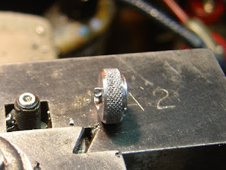
A smaller piece of steel, knurled and turned.

Tapping #8-32. The drawing calls out #8-36 but I'm a rebel. This does have implications down the line...

Parted off.

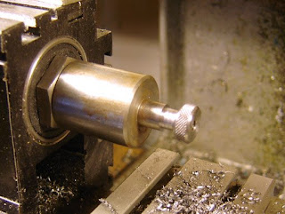
Mounted on a mandrel for facing off.

Done!

Now the aperture. Turned to diameter.

Threaded #8-32

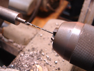
Drilling the major diameter. I reduced it a bit from the drawing to take into account the deeper thread depth of the #8-32 over the #8-36 (A difference of .003" thread depth)

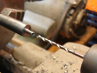
Drilling the aperture hole. I also reduced this, but mainly because I like a smaller aperture.

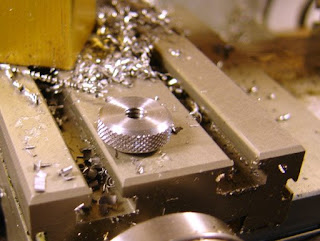
Knurling.

Parted off.

Blurry picture of boring out the face.

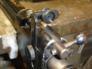
Blued with Oxpho blue and mounted on the rifle. Works fine. It's a fun and accurate rifle to shoot.

Thursday, April 30, 2009

Fabricating a Replacement Sight for a Crosman 101, Part 2

On I go.

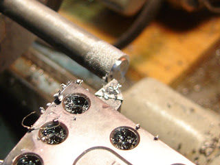
Knurling some steel.

Turning down to one diameter.

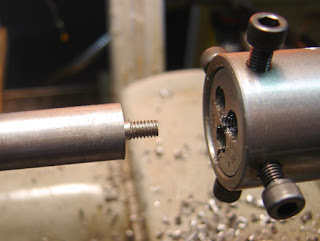
Then to the screw diameter, and threaded with a die.

Undercutting the thread. I probably didn't need to do this but it's on the drawing...

Parted off.

Mounted on a mandrel and the end faced and chamfered.

Slotting a screw slot.

The drawing shows that it's a plunge in from center rather than a straight cut. Not that it matters.
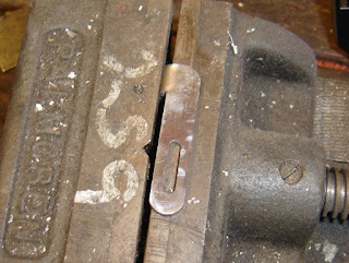
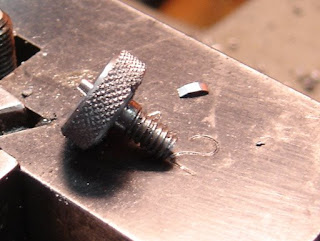
The finished screw.

It mounts the sight bracket to the rifle.

Wednesday, April 29, 2009

Fabricating a Replacement Sight for a Crosman 101, Part 1

As I mentioned before, I have three Crosman 101s. One worked fine and had been resealed by the previous owner but was missing the rear sight. So armed with D.T. Fletcher's parts drawings CD I decided to fab up a replacement. Unfortunately the drawing for the later model bracket was not supplied so I had to extrapolate from the early drawing and some pictures. This led to a slight mistake...

A piece of steel covered in layout blue was propped against my Taft Pierce box parallel, on my surface plate.

Scribing some lines...

Lines all scribed to my drawing.

I marked the parts to be removed (little x's) and scribed some radii.

Cut out most of the waste on the bandsaw.

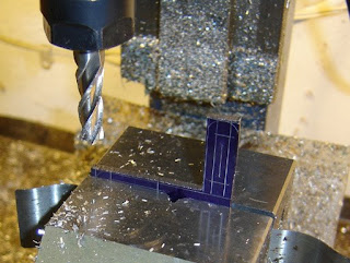
Milling to the lines.

Needed a tall endmill...

Milling the slots.

The radii were ground on my belt grinder.

I thought my Di-Acro bender would handle the job...

But I ran out of bend...

So I had to finish the 90 degree bend by hammering in a vise.

The bracket. This is where I made my mistake. The bend should have been 90 the other way. On the old bracket the bend (not really a bend as the whole thing is stamped to shape) is this way, but not on the newer one...shouldn't matter much functionally but it is wrong.

Mounted to the rifle.

Polished and deburred.