Saturday, June 28, 2008

Covering Up The Front Sight Grooves

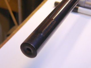
The Original (Diana) 45 has stamped grooves for the front sight, both on top and below (why?) at the front of the barrel.

I didn't want to remove them on the off chance I ever get a set of the original, Original, sights. But left as is they are ugly and not entirely comfortable to grasp while cocking.

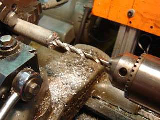
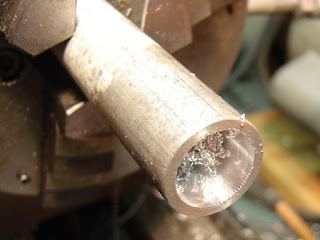
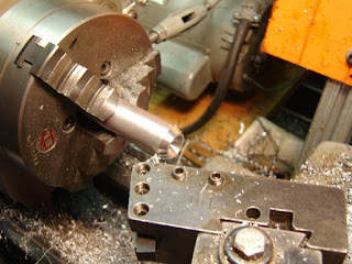
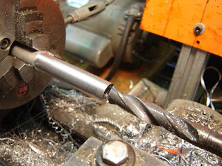
So I drill.

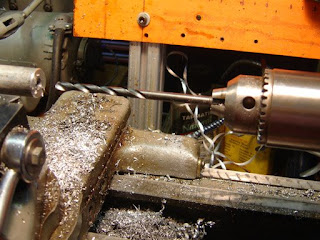
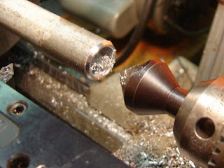
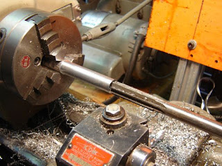
And then drill deeper.

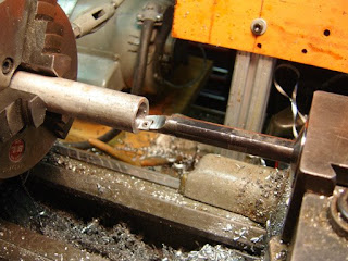
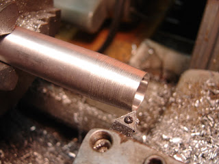
And bore to clear the grooves.

Boring picture of a bored tube.

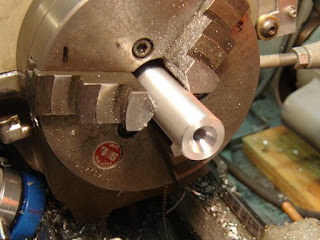
Deburring the hole with a large countersink.

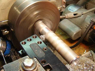
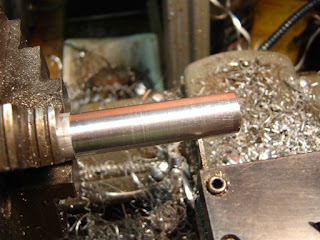
Turning down the OD.

And parted off the rod.

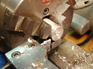
Flipped around it gets a rather large countersunk bore.

I thought I'd go for a minimalist tube look, but I didn't like it.

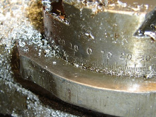
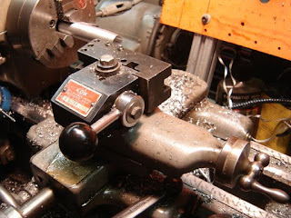
So I set the compound to about 3 degrees.

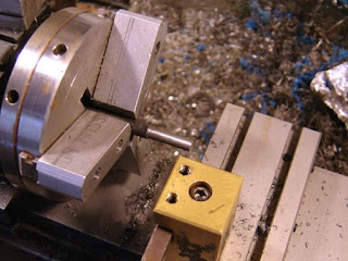
And turned a taper on it.

I took passes until the thinnest part of the tube was about .03"

Flipped and tapered in the front to about 60 degrees.

Making shims for the barrel.

Reaming to the diameter of the barrel.

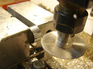
Parting off two bushings.

Slitting the bushings.

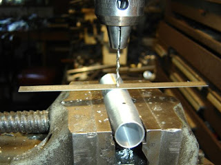
Drilling for two #4-40 tapped holes. Using a ruler in between the bit and a round workpiece will show whether the drill bit is centered.

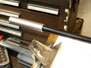
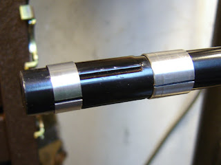
The shims on the barrel. These center the brake and protect the barrel from the setscrews.

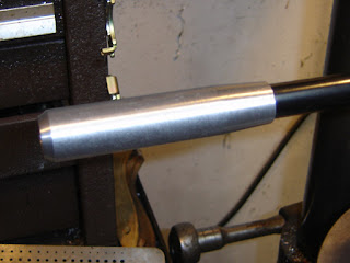
The finished brake (really a barrel protector and cocking handle). It's a bit big, but sort of has to be due to the front sight grooves. So while I don't like it on aesthetic grounds, I have to admit it is comfortable to use when cocking the rifle.


If I was really cool I'd send it out for anodizing, but instead I'm hitting it with some semi-gloss black paint. It seems durable on the Diana 6 pistol frame, and will be more easily touched up.

Thursday, June 26, 2008

A Small Puzzle

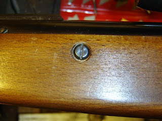
So the stock screws in the forearm of the Original (Diana) 45 bear on the wood of the stock. I want to make some nice screw cups that will spread the load, as well as looking pretty.

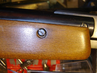
The first problem is that the holes seem off center. I can of course make off center screw cups, but I have a feeling it would look odd. It's possible that the screws can be tweaked a bit to center, or I can enlarge and center the counter bored hole.

The other side. Now in order to figure out what would be the best option I have to remove the action from the stock. Will I have enough wood to remove a bit more? Is the action fully bedded, etc?

The problem is that there is a pin that goes through the action in the rear, through two washers in counterbored holes. Now it's entirely possible I can just drift the pin out and remove the action but it's also possible that drifting the pin out will cause springs, tiny parts and other items to fly out as soon as the action is removed from the stock...so I have to do a bit of research.

Tuesday, June 24, 2008

A Scope Stop for the Original (Diana) 45

So the scope mounts taken care of, I turned my attention to making a scope stop. With powerful spring piston guns a scope stop of some form is needed to prevent the scope mounts from moving under the recoil. It is worth noting that scope stops can be purchased for very little money, but having less than that in my budget I set to work...

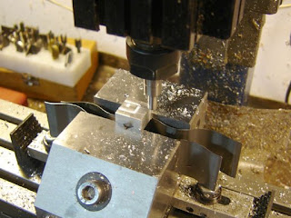
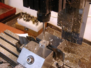
Finding the edge of a .625" x .625" x .375" block of aluminum.

Milling the minor width of the dovetail slot.

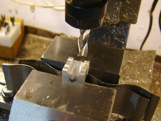
Milling the dovetail with a 60 degree dovetail cutter.

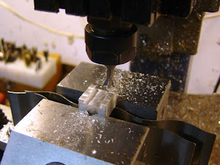
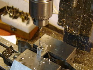
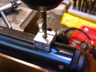
Drilling the hole for the stop pin.

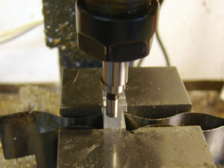
Reaming the hole for the stop pin. The reamer is held in a collet because of the lack of z-axis height on the Taig mill.

The work is flipped 90 degrees and the edges picked up again with an edge finder. Note the offset of the tip, this is what it looks like when it "kicks" out at the edge.

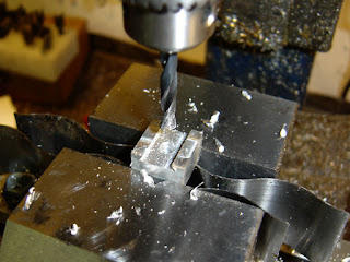
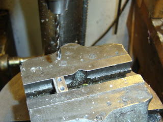
Drilling for the screw holes.

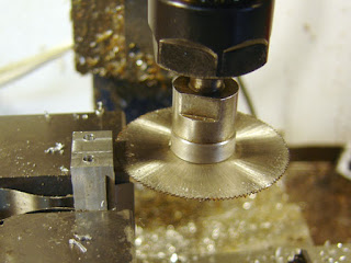
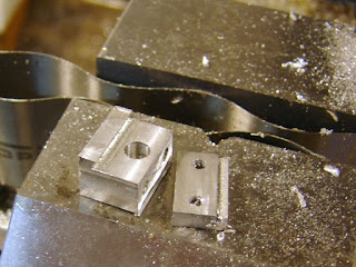
Sawing off one side of the dovetail. When I make another one I'll saw off both edges for better centering of the pin on the dovetail, but that's another story...

The two pieces.

Drilling the clamp part for #6 screw clearance.

Almost finished...but not.

I found that adding several washers maintained uniform clamping.

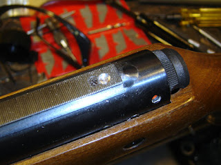
I then drilled a shallow hole in the scope rail, using the scope stop as a jig. I followed the drill up with an end mill to generate a flat bottom to the hole.

As you can see the hole is a little off center, as I said, it would have been better to make the stop adjustable for center.

Drilling the hole unfortunately wallowed out the carefully reamed hole in the stop, so I couldn't use a dowel pin as I planned.

So I made a pin out of some steel.

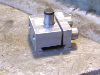
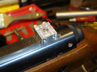
The completed stop. To prevent any movement, I used a small amount of loctite bearing retaining compound to lock the pin in.

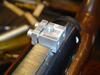
The scope mounted again...I made small witness marks so I could keep track of whether the stop moves at all. As with all my mistakes, er, experiments, I'll report any movement after I fire a few hundred pellets through. Today's post on the Pyramyd Air blog shows what can happen if movement does occur in a stop like this, but I think the addition of the loctite will prevent that.

Saturday, June 21, 2008

A Scope Mount Experiment.

I traded for an Original Model 45 (Diana) rifle a while back. The rifle came without sights or scope, so I wanted to mount a spare 4x scope on it. Being both lazy and cheap, I didn't have the correct scope mounts on hand, but decided to make do with a pair of B-Square 3/8" airgun mounts bought at the local gun shop for $10.00. I also wanted to play with tying the two mounts together.
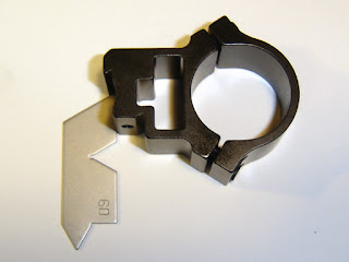
First I checked the dovetail angle of the scope mount.

The scope mounting rail on the rifle seemed to be 60 degrees, or close enough...
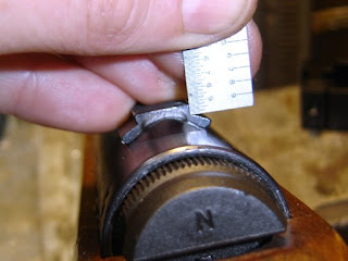
The height of the rail is just about .08"
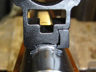
With the scope mount on, contact was only being made at the bottom corner of the dovetail.
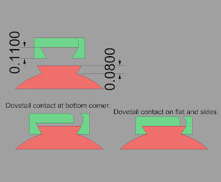
Generally, at least in the world of machine slides, you want better contact than just one plane. So I decided to cut about .03" from the bottom of the scope mount dovetail, which would allow the scope mount to contact the rail on the side and the top. This should both increase the forces on the rail, as well as keeping the scope mount perpendicular, rather than canting to the left or right.
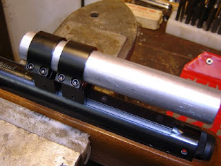
I had a 1" diameter bar of aluminum and clamped it in place of the scope. This allows keeping the two mounts in alignment.
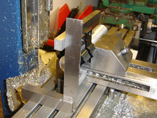
This was put in the vise and using a square and a parallel, I got it pretty close to perpendicular.
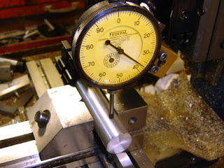
Then using a dial indicator I made sure it was level to the machine travel.
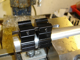
I inserted some shims (.01") to keep a load similar to that of the clamping forces on the dovetail clamps.
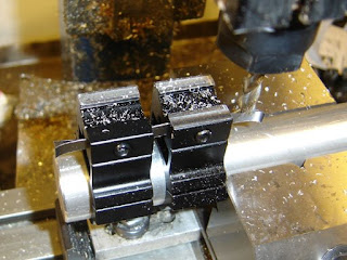
This was interesting. I took off .005" and one of the clamps didn't get touched.
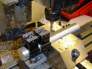
I continued machining down to .03" depth of cut.
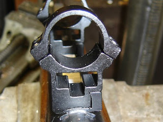
The mounts now are solid against the top of the scope rail.
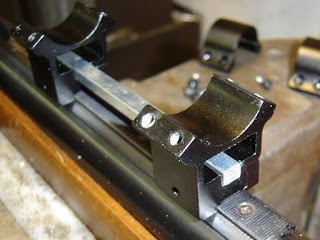
I had some key stock that was a nice fit in the "see through" groove in these mounts.
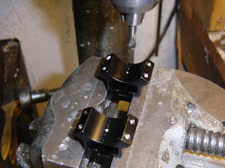
I spotted for holes on the center line. At this point you are likely yelling "Stop Nick!". Bonus points for figuring out where I'm about to go wrong.
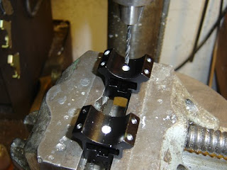
Drilling through for a #6 tapped hole.
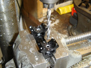
Drilling a clearance hole through the mount.
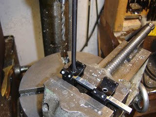
Using the transfer punch to locate where to drill on the key stock.
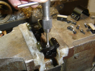
Tapping the mount.
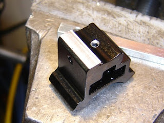
At this point I let loose with a stream of salty and impure language. Yes, I forgot about the clamp screw, which goes right through the middle...
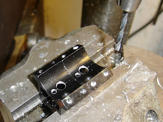
So I relocated the holes for clamping the key stock...and redrilled the holes offset in the key stock.
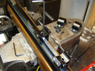
Screwing the key stock to the scope mounts.
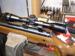
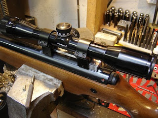
The mounted scope. I still need a "scope stop" as this springer has quite a bit of recoil. That will be the next project.
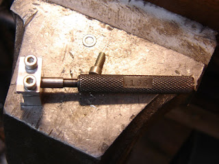
Note that I was not concerned with any windage offset on the mount due to the widths being different, nor was I concerned with "droop". As it turned out I had more than enough adjustment in the scope to get it shooting dead on. Windage could be corrected by taking a dovetail cutter and taking a bit off of the fixed side of the scope mount dovetail, and "droop" well, there are a number of ways to deal with that, such as reboring the rings, recutting the dovetail, or making a sub-scope rail that had the proper angle...but best to not think about such complexities...