Tuesday, October 14, 2008

Derrick Works his Magic on a Crosman 38T, Part 3

Derrick's chronicle continues...
So my lack of a plan almost caught up with me. I "conveniently" forgot that the frame of the 38T is 3/4" thick. There would be no way to just set a pair of "match" grips onto that thick of a frame. What was I thinking? Well, I was probably thinking that when I first saw the 38T I thought how nice and easy it would be to make some exact replacement grips. Which is true. This gun would be an excellent candidate for a nice pair of custom grips with minimal inletting--Unless you decide to make target grips--Then you have to make the frame fit INTO the grips. I think I've still got enough wood here to go forward. In retrospect, I should have inletted first, THEN gone to the scroll saw. At this point, I'm forced to fit the right side grip (because it has the least amount of material in the heel) first and that will dictate the left side's profile. I would have proceeded this way regardless, but I should have thought further ahead. I think my next move is to screw through the right side grip holes into the left and work some of the external dimensions as a whole unit. I've not yet figured out how to attach the left grip to the frame. The stock grip simply clips to the CO2 cartridge.
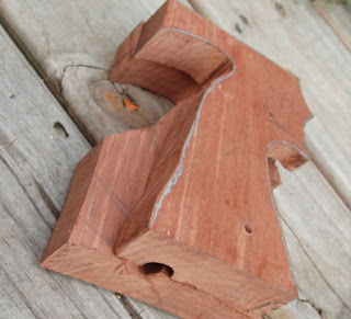
No, that's not dykem. It's just a silver magic marker. It shows up well under the sawdust as you're cutting.
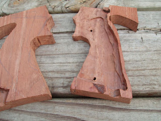
The inside won't be so pretty. I used a 30,000 rpm trim router for this.
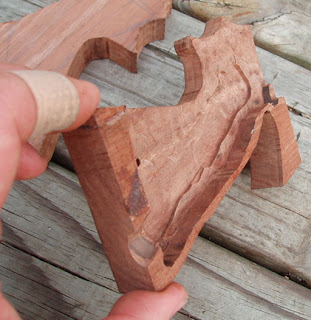
3/8" deep routing. Test fitting looks promising. I no longer wonder why Nill-Griffe gets $250 for a pair of these. You really need a milling machine to inlet something like this. http://www.nill-griffe.com/
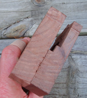
For the most part, the right will dictate the left. A palm shelf will come last. One bolt slot for the shelf or 2? More to ponder. And yes, I cut myself with a razor knife while scoring the walnut so the router didn't rip the corner off.
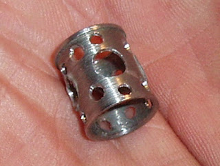
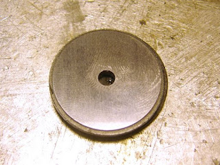
Here's my valve volume increase. Inside the valve, the sleeve serves to provide a base for the o-ring (140-058) and valve seal (38-094) to seat against. Just make this into lattice. Of special note: It's working. The pellet holes are substantially cleaner as they cut through the 10 meter targets. If I take it apart again, I'll try drilling a few more holes-- or it'll be slotted. I tried hanging a piece of tissue over the cylinder and looked for CO2 leakage at the transfer port as well as at the cylinder gap to the breech. Let's just say I've never seen a revolver so tightly fitted that it still functioned. On one hand I'm happy I was able to virtually eliminate any wasted CO2. On the other hand, it's getting harder to find any more power. I think I need to revisit that valve spring and see just how weak it'll go and still function.
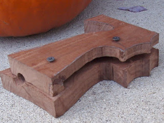
Now that the right grip has been inletted to fit the 38T's frame and the mounting screws have been located and drilled on the drill press, I've screwed the two halves together to shape the common sides.
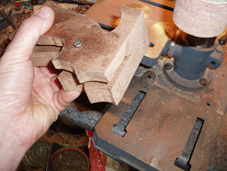
I chucked a 2" diameter sanding drum into the drill press and dropped the rpm. If you try to go too fast, you'll just burn the wood's surface. This let me sand the top, front and base as one piece. It'll fit tighter together this way and help eliminate unsightly gaps at wood to wood junctures. I used a charcoal mask while sanding. Black walnut can be an irritant to many people when inhaled.
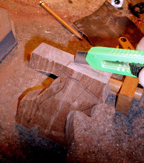
Time to inlet the left grip. I laid the gun's frame on top and traced. Scoring the line with a razor knife helps prevent the router from ripping out more wood than you intended to remove.
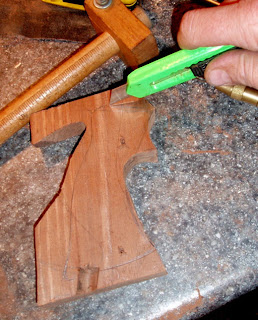
More scoring.
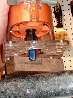
The trim router. Categorically the most dangerous shop tool I've ever used. 30,000 rpm helps keep the blade from tearing the wood. Whatever happens to the workpiece, do not under any circumstances let go of this tool. It will jack you up. It is extremely helpful from a control standpoint to get to full depth in several increasingly deeper passes. This tool is literally a wood eraser.
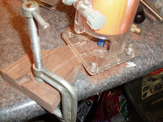
Anchor the work. Go slow and easy and you can write your name into the wood.
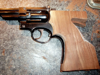
Test fit. The inletting is, to me, the worst part of the job. It's also, unfortunately, the important part because it defines how good the project will ultimately look. I am by no means good at this. I'm learning an awful lot as I go along. It helps that I have a few airguns with adjustable match grips to compare and pick the best features from. One of the challenges with a revolver is the bore height in relation to your grip. Getting your hand higher on the gun is better for recoil control as you get less torque from the muzzle blast. A non-issue here, but the lower sighting plane feels more natural. The "wing" at the top of the grip will be necessary once the adjustable palm shelf gets added later. The goal with a match grip is to envelope the hand and provide outstanding ergonomics for both sighting and control.
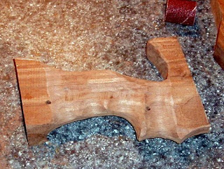
Back to the sanding drum. I used several smaller diameter drums to make the corners disappear and round the overall profile. Constant transfer to your gun hand ensures that it fits you. It's customary on the firing line to see match guns with wood putty, rasp marks and skateboard deck tape on the grips. Just making the tool fit.
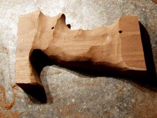
Roughed to shape.
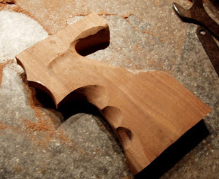
Left grip roughed to shape. Far less to do to this side.
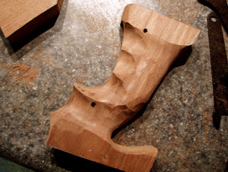
Slightly further along on the right grip. The finger notches are starting to show more definition.

Monday, October 13, 2008

Derrick Works his Magic on a Crosman 38T, Part 2

Derrick's chronicle continues...

Left side: Original .177 cal pellet cylinder. Center rotation hole is 1/8" dia. Right side: Ebay purchased. Bored out for .20 cal pellets. Center hole is 13/64".

Need to either bore the original cylinder out to .20 cal or make a bushing for the replacement cylinder. I'll try the bushing route first.
First, I turned down a piece of round brass stock to fit the bored out cylinder.

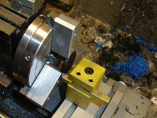
Facing off a brass rod. Yeah, I know there's other tools for this. It was already in the tool post and it cuts like a laser beam. I made the tool to crown barrels.

A slightly blurry pic of the drill at work. Is there an easier way to drill holes in the center or round stock? Nyet.

Bushing installed. It was a snug fit to start, so I added a little super glue just for overkill. It's not going anywhere. The pin keeps it captive as there's not enough room for it to back out.

The 38T's new .20 cal barrel cut to final length and a target crown.

Oh dear God, what am I getting into? I've got minimal woodworking ability. Wait. I've just got minimal ability.

Everybody was kung-fu scroll sawing. It can (will) only go downhill from here. It was a perfectly good walnut board until I got hold of it.

Thick and chunky! You'd probably think I had a plan before I wasted $12 worth of walnut and precious time on a gun that doesn't shoot fast enough (yet) to cut clean scoring holes in a 10 meter target. Well, you'd think....

Sunday, October 12, 2008

Derrick Works his Magic on a Crosman 38T, Part 1

Derrick, our Ohio correspondent, is at it again, modifying a Crosman 38T.

Self-centering. Not the stock cylinder. Ebay! Nobody named Derrick noticed the big hole in the middle of the cylinder till later. I had no idea that Crosman used two different cylinders in 38Ts. They both started as .177 cylinders. Just over 1/16" in hole diameter difference. This one is too loose on the pin. Need to turn a bushing later.

Brass Crosman SSP 250 barrel in .20 cal.

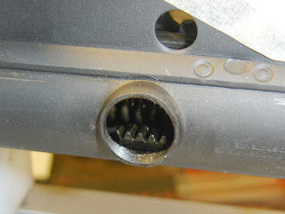
Holy cow! Udder madness. The inside of the shroud tapers? I think they were trying to put weight (metal) at the muzzle without using a heavy barrel. I bored the muzzle end out to 7/16"--to match the OD of the new barrel.

Taig time. Crowning the .20 cal bbl. Also cut the breech with a small taper to guide the pellet into the rifling. Notice that I re-faced my 3-jaw chuck faces. There was some kind of industrial accident that had previously rendered them "gouged". Also cleaned up the business ends.

I like the recessed target crown. It adds a bit of extra visual appeal for an extra minute or two of time. I've found that it's essential when finishing the crown's bevel to start from the center and work towards the outer edge. So many simple things that I have to figure out for myself. I'd never thought about how the metal pulls in the direction that you're cutting.

Groovy. The o-rings provide a press fit into the shroud's varying ID and effectively centers the barrel. 2 steps at the breech. I'm not sure why. I think I was going in a different design direction and made a change. The barrel is about 2" too long. Left extra length to allow fitting at the cylinder.

Much more to come...

Wednesday, October 8, 2008

Resealing a Diana Model 10, Part 6

Just the stepped washer to do.

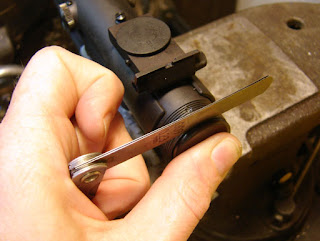
With the washer held against the rear piston seal I checked the gap with feeler gages. I showed .021" of gap. Going by my work on the Diana model 6, I want that gap to be .3mm, or .012". So I need to remove .009" off the face of the stepped washer. On the Diana model 6 I made a whole new stepped washer, which meant I could use the old Diana 6 washer for this purpose...

I chucked up the old washer and tried to face off .009...yikes! Totally hardened. Even with carbide I was having a very hard time removing material and getting a smooth face.

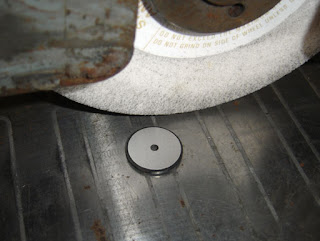
So I went out to my surface grinder and ground the face down.

A lovely smooth finish.
I replaced the stepped washer, checked the gap (it was right on) and screwed the end cap back on.

I ran a bunch of pellets through the chronograph, the last 10 shots with RWS 7.0 gr. Meisterkugeln gave me between 491 and 503 fps. That's about what it should be doing.

How accurate is it? Much more accurate than I am...time to practice.

Tuesday, October 7, 2008

Resealing a Diana Model 10, Part 5

And on I go...

I lightly coated most surfaces with moly, the spring got an extremely sparing coating of spring tar.

The pistons back in place.

The pinion caps were aligned with the screw holes.

I checked the depth of the cap with just the stepped washer, subtracted that from the measurement I'd taken before with the recoil seal in place.

I machined a new urethane rubber recoil washer.

I screwed the end cap back with the stepped washer and recoil washer to make sure that I had the washer thickness right for the screw hole to line up.

Now there's just the remaining detail of the thickness of the step on the stepped washer...

Monday, October 6, 2008

Resealing a Diana Model 10, Part 4

I made a special tool to put the seals on the pistons.

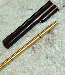
The tool is two pieces. A plastic rod 1/2" in diameter, with a taper on the end and the other end turned to be a slip fit in a piece of brass tubing. The brass tubing is polished on the end for about 5/8" of an inch. It's about 8" long because that's what I had in my box of brass tubing. I could have used solid plastic rod and just bored a hole to mate with the pointed piece.

The assembled tool.

The tool was lightly lubed with thin oil, and I pushed the seal on, backwards from the direction it would be installed on the piston.

The seal was pushed past the plastic tapered piece, onto the brass tube.

I removed the plastic piece and pushed the seal against the edge of the tube.

I held the brass tube against the end of the piston button, making sure it lined up.

I pushed the piston seal off the tube and onto the piston, where it settled with a lovely and almost inaudible click. This was by far the easiest piston seal installation I have ever done, and I will likely use a tool like this every time I need to fit a seal to a piston. I did the same for the other piston recoil seal/bumper.

Almost done...

Sunday, October 5, 2008

Resealing a Diana Model 10, Part 3

On I go...

The pistol action is held in the compressor.

I removed the end cap screw, then the end cap and the sleeve. The sleeve is for contact with the hand.

I used a depth micrometer to determine the gap between the rear seal and the end of the tube, .008". I also measured the distance from the end cap shim and the end of the cap, .422".

The pinion cap screws. I removed them.

I loaded the spring slightly with the compressor. As on the Diana model 6 I used my handy tool, a file tang.

With copper sheet to protect the cap I removed the right hand (looking from the top of the action) cap and pinion gear.

The cap and gear.

The rear piston rack in position.

Twisted up to clear the left hand pinion.

I slackened the compressor and the rear piston came out with the spring.

I pushed the front piston most of the way out with a .125 dameter brass rod through the transfer port. Then I was able to pull it out.

I think the front seal is bad.

The end cap shim and synthetic washer.

The synthetic washer was not in the best shape either.