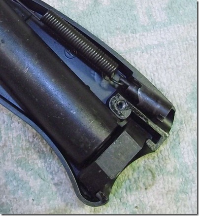
The power adjuster and spring that connects to the hammer.
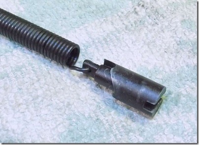
The power adjuster has three discrete notches around the periphery.
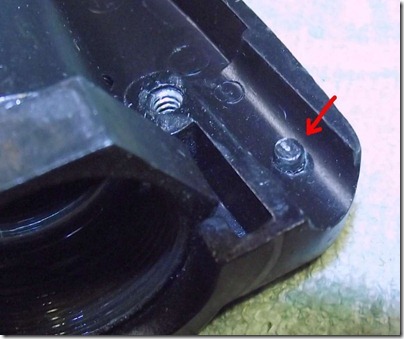
Which mate with the molded pin sticking out of the channel.
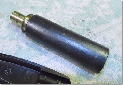
The CO2 cartridge chamber and valve assembly.
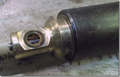
Notice the flat face of the exhaust valve.
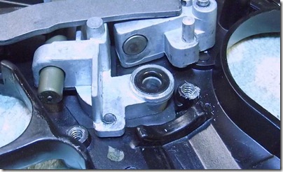
The flat face sits against the o-ring and gas travels through.
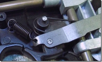
What the heck, let’s call this a sear.
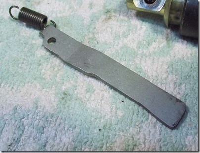
Just a flat bar with a dogleg.
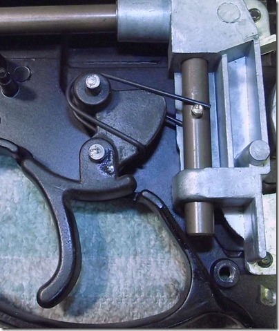
Notice the spring on the hammer passes above the pin in the BB feed mechanism in front and below in the back (relative to the orientation of the pin…)
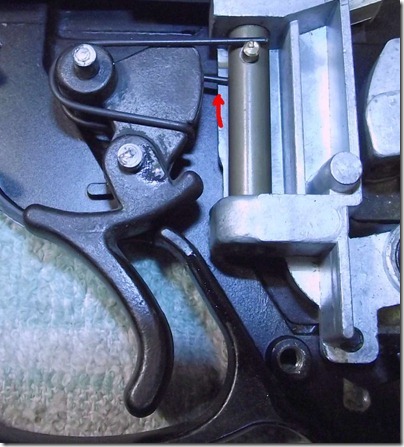
When the trigger is pulled it move the feed mechanism up.
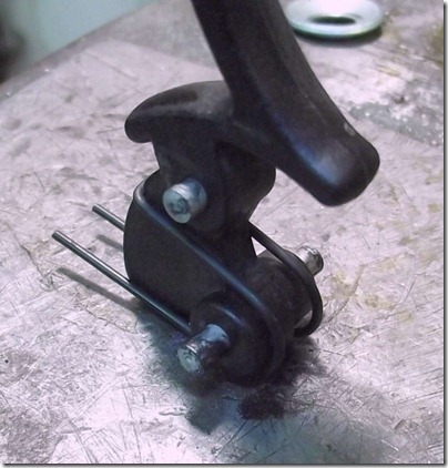
The trigger and spring.
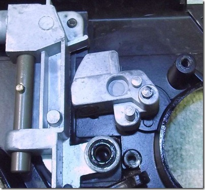
The hammer.
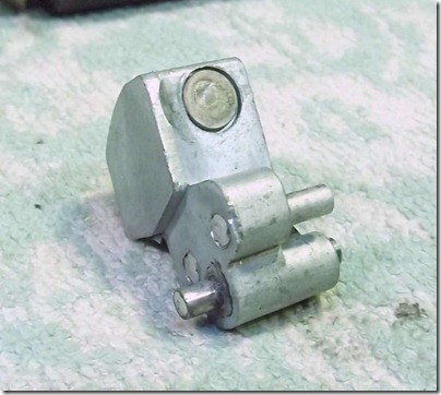
It has a steel insert.
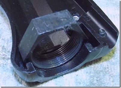
A large nut for the piercing cap sits in the frame casting.
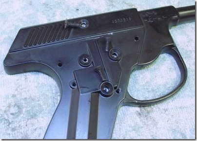
Right frame has three screws that are removed.
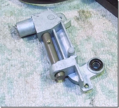
And the BB feed mechanism comes free.
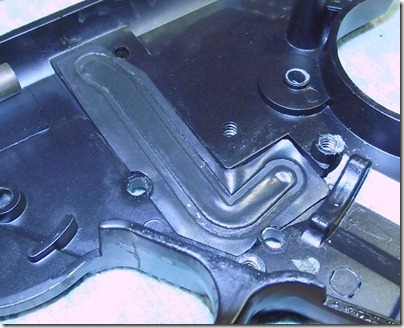
Huh, a flat rubber gasket.
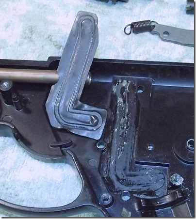
It was glued (probably with rubber cement of some sort) to the frame.
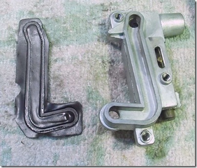
This is another first, the passage for the gas as it travels from the valve to the barrel is open on the side. The gasket seals it against the frame.
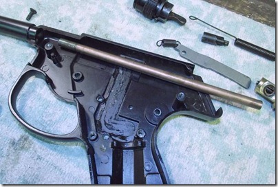
The barrel slides out. The barrel seems to be copper tubing but I suppose it could be bronze.
More to come…
2 comments:
Where does the long black pin go in this thing?
I got it
Post a Comment