Showing posts with label crosman 167. Show all posts

Friday, November 7, 2008

Mounting a Williams Sight on a Crosman 167, Part 2

So I need some longer mounting screws...

Turned and threads cut.

And cut off.

Slotting.

The lower base hole needed to be elongated.

As did the shim.

A tiny vise holds the sight blade (? insert?) and I slot it deeper.

And mill the top down. The goal was to have it roughly in the middle of the adjustment range when the rifle was zeroed at 10 yards.

I slapped some paint on the exposed aluminum. Mounted solidly. I think I could get away without using a shim if I could overlook the gap between the barrel and the base.

a bunch of shots to sight it in and then 5 shots in a row (only at 7 yards...too dark outside) pretty much on center.

Thursday, November 6, 2008

Mounting a Williams Sight on a Crosman 167, Part 1

I love my Crosman 167, but I absolutely hate the cheap stamped rear sight. Recently I bought a lot of random Williams rear sights on Ebay, for about $5.00 a piece. So I set about adapting one to the Crosman.

The Williams sight and existing sight. Windage is adjusted by loosening one screw and pushing the sight over.

Elevation adjustment is achieved by pushing in or out the notched ramp.

The Williams sight, while not a micrometer sight, has clearly marked index scales and is much easier to adjust.

Mounted in one screw hole, you can see that the other hole is not in the right place. I could tap the barrel, but I prefer to keep it in stock form (or easily reversible).

The sight base has too large a radius.

A piece of aluminum was turned to the radius of the sight base (I got it close and then checked until it seemed to have full contact.) Then it was offset eccentrically in the chuck.

Drilling begins.

Drilled out to 1/2"

Then to 9/16". The Taig isn't ideal for drilling with larger drills, but in aluminum it works fine.

Parted off.

With a plug inserted, and held in a vee block, the eccentric piece is adjusted.

Sawing off my shim...

The shim fits perfectly.

The underside.

Marking one screw hole.

More to come...

Tuesday, September 23, 2008

A Valve Stem Seal for the Crosman 167, Part 2

So, on to the valve.
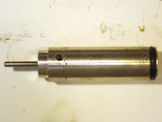
The valve assembly was pushed out of the tube.
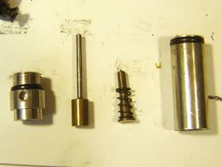
The valve assembly, disassembled.
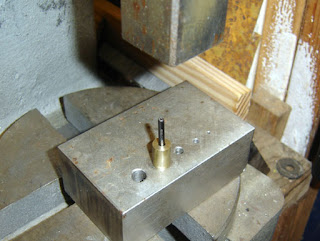
I used a short dowel pin to press the valve stem out.
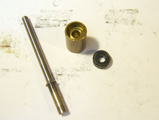
The disassembled valve.
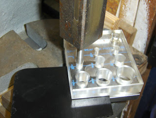
Using the directions in Airgun Hobby Vol. 2, Number 3, on page 43, in an article titled "How To Make and Install Your Own Valve Seals" by Peter Ruut, I stamped out a 5/16" diameter disc from 1/8" thick 95 durometer urethane rubber sheet.

However I found that stamping the disc made the edge of the disc concave. This didn't seem ideal to me. I'm not sure why this happened, but will chalk it up to differences in material supply, ambient air temperature and possibly my use of an arbor press instead of a hammer...
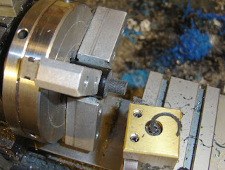
So I turned down some 95 durometer rod to 5/16" diameter.
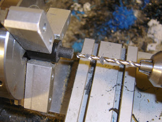
And drilled the hole for the stem.
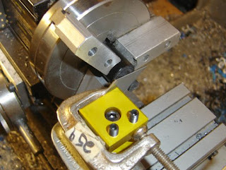
I clamped a utility knife blade to the toolpost and cut the face off.
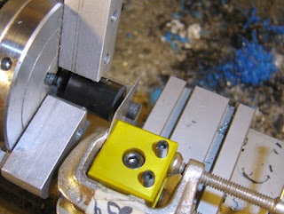
Then cut it to length. This worked well and gave a very smooth surface. I think I'll make a dedicated utility knife holder for the lathe.
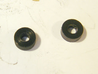
The new seal on the right, old on the left.
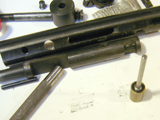
I pressed the valve back together. Notice the bolt in the picture with the cutouts for the cocking pins.
I assembled the rifle and it held gas! Two days later and it's still holding fine, so I'm calling this repair good. I did replace the other o-rings as well, which certainly didn't hurt.

Monday, September 22, 2008

A Valve Stem Seal for the Crosman 167, Part 1

My Crosman 167 has a slow leak. If left for a few days the CO2 empties out, and the likely culprit is the valve stem seal. So I decided to take the valve apart and see if I could make a new valve stem seal. See here for the exploded view. Mine is the first variant with the simple trigger and no front barrel band. It should have an automatic safety, but that part is broken and I have yet to make a replacement.

The action removed from the stock.

The underside.

The valve screw 160-26 is removed.

The screw that holds the end cap is removed. This is where the automatic safety would be if mine weren't broken.

The setscrew that holds the bolt handle in the bolt is removed. My bolt handle is polished because the previous owner thought the bolt handle unscrewed from the bolt, thus marring it horrendously.

Removing the stud 160-10 which holds the action on the stock, and holds the valve spacer 160-7 in place.

The setscrew that holds the barrel in the receiver is removed, as is the barrel.

This reveals the screw 160-32, which also holds the 160-7 spacer in place, and attaches the receiver to the gas tube.

The receiver is removed from the tube. Left stud engages the cutout in the bolt on the left and the right stud (with square head) the cutout on the right. This allows the hammer to cock on closing. Opening the bolt pulls the hammer to the right where it is caught by the sear, and closing the bolt compresses the hammer spring.

The hammer assembly. The pins are a slip fit in the holes.

Spacer 160-7 with the stud and screw. It slides out of the tube when those two are removed.