Saturday, January 16, 2010

Taiyo Juki (EIG) Junior Disassembly, Part 1

This last November I was surfing Gunbroker and one of the listings caught my eye. The title was: "EIG .177 Cal Pellet Rifle"

I'd never heard of EIG but looking at the picture and description it seemed to be a Taiyo Juki CO2 powered rifle. The Buy It Now price was quite cheap so I snapped it up. Looking in The Blue Book of Airguns I found a picture of the Taiyo Juki Junior that was an exact match. The Blue Book doesn't make any mention of EIG as far as I can find. The Blue Book says that the Junior is "similar to Bobcat" and under the Bobcat it says "similar to Crosman Model 160". In reality the Junior is much closer to the Crosman 180, as we will see.

As to why the title of the auction said EIG and not Taiyo Juki? The rifle itself is not marked Taiyo Juki or Junior anywhere, just EIG Cal..177 Made in Japan. So what was EIG? EIG was EIG Cutlery, an importer of knives and firearms based down in Florida. The same EIG is the last name of the then owner, Saul Eig. There's tidbits of information around the web about EIG but nothing I could find about their airgun imports.

As for Taiyo Juki? There's a bit more information as their parent company, Miroku Corp. is still in business, but they don't have any information about their airgun offerings (at least in english) on their firearms division webpage. I have seen other models of Taiyo Juki mentioned on the various airgun forums but nothing much on the Junior.


The rifle. I really need to set up a method for photgraphing whole rifles that's more aesthetically pleasing.

EIG CAL..177 JAPAN

The serial number?

The cocking knob (just as with the Crosman 180, it cocks separately from loading.)

The bolt.

The front sight is milled from steel.

It has a flow through bolt nose. The gun was full of sticky grease for some reason.

Since it likely needed new seals and was greasy and dirty I started to strip it down.

Rear trigger guard wood screw, front a machine screw into the action.

The trigger spring springs up.

And the stock comes off. Just the one screw holds the stock to the action.

The CO2 tube cap. That o-ring looks pristine.

The barrel band is coarse plastic and seems shoddily made compared to the rest of the rifle.

An extremely simple trigger and sear.

One screw from the bottom into the cocking assembly.

removed.

It's the short screw, if you're keeping track at home.

Flipped right side up, another screw through the barrel into the cocking assembly.

Which is the long screw.

The assembly comes out easily.

Greasy. The assembly seems to be of good quality.

I tried to remove that screw but the rod down the center just spins. No desire to destroy anything so I left it alone.

There's a power adjuster screw.

And the hammer has a small extension that actually hits the valve stem.

More to come...

Wednesday, January 13, 2010

Daisy 717 Trigger Refinement Part 2

Note: This modification dramatically alters the sear contact creating a dangerously light trigger. The gun will fire if dropped. It might fire if not dropped. Don't do this unless you take complete responsibility for what may happen. Seriously, don't try this at home.

The sear polish was helpful, but still not quite what I was after. I disassembled the trigger components again and dug in. Started by sanding the mold lines off the sides of the plastic trigger.

Used a piece of 1200 grit wet dry on a granite block. Just took off the high spots so there's no drag inside the grip frame. Not shown: Finished by buffing the sides on a sheet of thin cardboard embedded with Mothers Mag and Aluminum Polish. The sides were glossy when finished. Also not shown: Polished the inside of the grip frame with a fine Cratex abrasive wheel in the trigger area.

On to the Nygord trigger modification.

Spotted the inside of the grip frame with a center drill.

Then through drilled with a #43 (0.0890") drill bit.

Another view.

Since the #43 bit was still in the drill chuck, I measured the forward tab on the trigger. Divided by two and found the centerline and eyeballed a good spot just behind the tab for the safety.

Then drilled through.

Followed up with a #4-40 plug tap.

#4-40 set screw installed. This will function as a positive trigger stop inside the grip frame to limit trigger travel after the sear releases.

Tapped the frame with the same #4-40 size.

A dab of Dykem layout fluid on the bottom of the sear...

Like so.

Installed a 1/2" long #4-40 set screw,

and reassembled the trigger components.

Manually cocked the sear/cocking link, then turned in the set screw until I felt it "bite" into the bottom of the sear leaving this small mark in the Dykem.

Mounted the sear in the Taig lathe milling vise.

Used a 3/32" center cutting mill

And created a small shelf for the #4-40 set screw to bear against.


Reinstalled the trigger parts. This is the sear at full factory engagement.

By turning the set screw inward, it presses against the small milled flat and moves the sear backwards away from the cocking link. This decreases the sear contact and makes the smallest trigger pressure fire the gun.

The sear contact is literally on edge. This trigger adjustment will likely not hold up long term. The sear and cocking link are made from what appears to be die cast zinc or an aluminum. Why Daisy didn't use case hardened steel here is beyond me. However, Daisy didn't engineer this trigger to last with this little sear contact.

I've been warned that the set screw adjustment tends to wander over time, so I used a very low grade thread locker on the screw. The amount of screw movement to affect trigger pull, by the way, is extremely small. It only takes about one full rotation on the screw once sear contact is made to fire, with the correct adjustment being just before firing. So, any setscrew movement at all is detrimental to the trigger pull. Though, if there is movement, the set screw will only move downward--increasing sear contact. If I were to do this modification again, I believe a finer thread pitch on the set screw would be beneficial as there would be less travel on the sear per rotation. It would be easier to achieve sear adjustment.

Kinda blurry, but the trigger stop set screw is adjusted inward until the trigger will not fire then backed out incrementally until it does. Erred on the side of trigger function. I backed the screw out about 1/8 turn after the sear released.

I never would have believed that the 717 trigger could be this good. There's zero creep and a crisp release that's hovering around one pound.

Tuesday, January 12, 2010

Daisy 717 Trigger Refinement Part 1

I've been procrastinating over several airgun projects lately and my lack of posts shows. It's been about 10 degrees in the garage and I can't get any enthusiasm to freeze my tail off. I need to finish the Daisy 717 that Nick sent. With the valve repaired, I've been shooting it almost every day. The trigger is almost the only thing holding it back from being a good cheap 10-meter contender. (OK, it also could stand another 50 fps to cut cleaner holes for scoring)
There's a well-known trigger modification out there credited to the late Don Nygord. Nygord was a world-class pistol shooter. When the best shooter in the world says "do this to the trigger", we should pay rapt attention. By the way, Nick previously covered this trigger modification. Why am I covering it again? Well, I haven't done it, my gun needs it and I'm not working on much else.

Pulled the grip frame and removed the grips.

Knocked out the pin holding the sear, sear block, and cocking link,

and they pull right out.

Removed the sear spring from the two parts. The sear is on the right and goes to the front of the gun. Cocking link on left. The spring had flaking red paint all over it. I removed the paint and lightly greased the spring.

Polished all the contact surfaces on the buffing wheel.

Before going right to the Nygord modification, I wanted to see what a polish and lube would do for comparison.

Greased the sear/cocking link interface with some Psycho Lube.

Also greased the pivot pins and the sides of the bosses where they pivot against the inside of the grip frame. Reinstalled and ready for action.

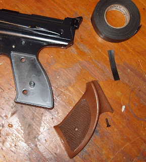
One more thing while the grips are off. The top edge of each grip is supposed to fit under the receiver snugly. These don't and the grips are quite loose.

Cut a strip of rubber splicing tape...

Yep, you got it.

and notched it to fit around the small post at the top.

The rubber makes for a crush fit at the top.

No more play! Hit the right grip with the same treatment.

The trigger pull is much smoother but it still has a fairly long take up. So, I brought the drill press into the house to warm up. Nygord, you're up next.