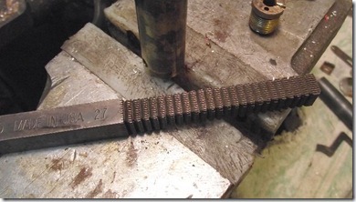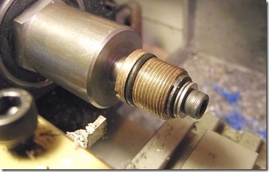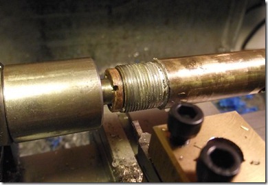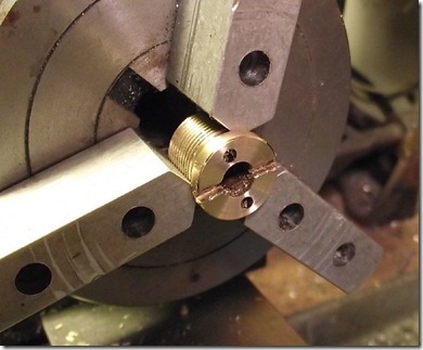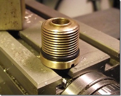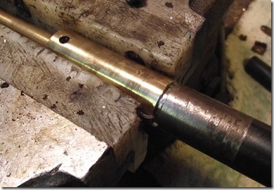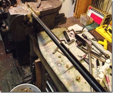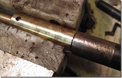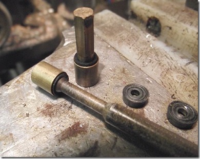
Bolted a couple 1-2-3 blocks together and placed the original mag against the soon-to-be. This arrangement kept things relatively square while I marked the angle across the corner. The angle appears to be for ease of insertion into the mag carrier on the gun. Not shown: milled and finished the angle.

I set up the original mag in the milling vise and used it to set up the quarter round cut. The depth of this cut indicates the mag in the carrier. I used a depth micrometer set against the lower fixed jaw on the vise to position the work in the same location.

Used a 4mm end mill then test fit the mag in the gun. It was a good fit in the carrier. A bit tighter than the original.

Not exactly an epiphany, but I've been thinking a lot about how to mark off the pellet hole spacing on the mag. It occurred to me that I could simply remove the barrel...

and just use a transfer punch to mark directly though the breech.

Put some layout fluid on the face of the mag, then slid it home.

Lucked out and had a punch that fit the breech like it was made for it.

Tap, cycle the carrier manually. Tap, cycle the carrier...

Testing: Drilled some aluminum with various sizes of bits then tested .177 cal wadcutters in the holes. No real surprises here, but I settled on a #16 bit for final size.

A pointed indicator is used to locate the center of the hole...

then it's replaced with a bit and through drilled.

Then back to the indicator for the next hole. Slow, but it worked.

Opened the holes up to #16 (0.1770").


Used a #15 bit in a pin vise to chamfer the breech side of the mag to allow the pellet skirt to seat flush.

A small groove cut with a 1/4" ball mill marks the side to load.

Front view. Test firing was surprisingly uneventful. The darn thing functions and the pellets go into a little tiny single hole on the target--??? I am utterly astonished that this even cycles--let alone works. Oh, the bottom mag is the new one. I'm absolute proof as to the old saying about blind pigs and acorns.
