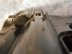
After the first 600, taking apart the other one is easy.
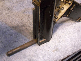
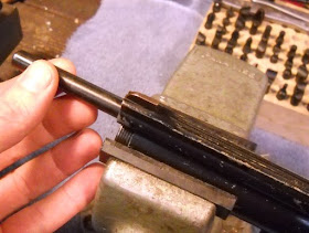
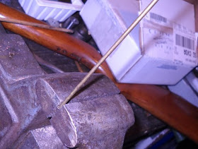
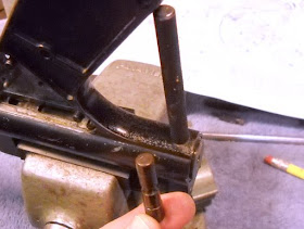
First I took a 1/8" rod and bent the end in a vise.
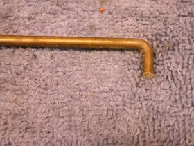
To make a hook like this.
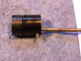
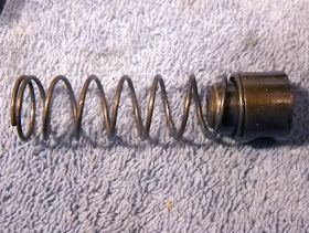
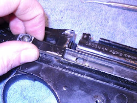
So I could pull out the 600-102 piercing assembly...
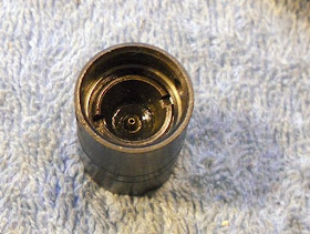
Standard 38 style piercing pin and seal.
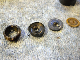
Somewhat worse for wear.
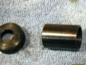
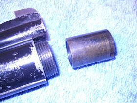
I forgot to take a clear picture of the tube cap. This one has a hole the end of the CO2 cartridge sits in.
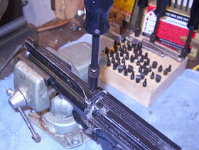
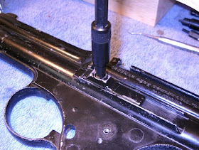
Since I had one valve front out I measured the screw slot and milled a cheap socket to fit.
The front valve parts.
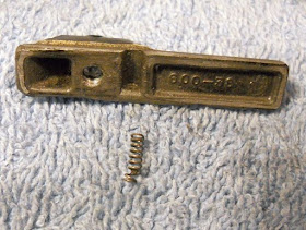
The feed arm. There's another setscrew under the first.
Much better shape than the other one.
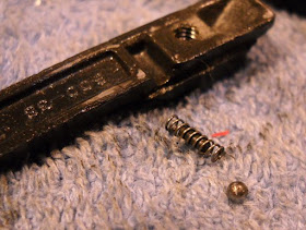
It also has the proper spring, ball and guide for the slide.
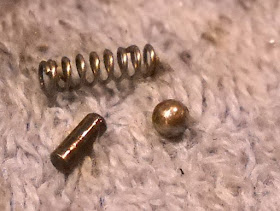
The guide is just a tiny dowel pin.
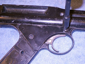
As you can see the trigger guard is broken. Also that tiny piece fell out when I removed the cover plate...
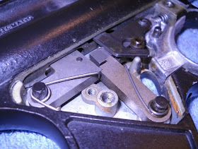
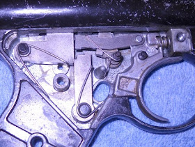
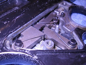
Some more gratuitous shots of the trigger mechanism.
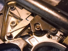
Notice that this trigger group has the stop and stop roller. I'm still not clear why these were added to the design (or were they removed from the design?)
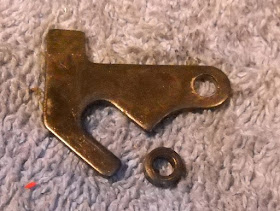
Stop and stop roller.
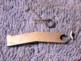
The link is the source of that small broken piece. Not sure how that would happen?
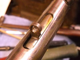
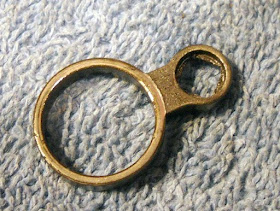
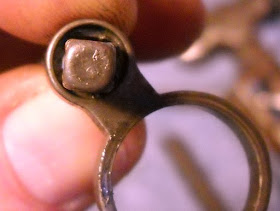
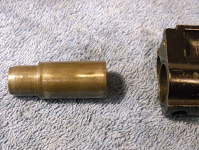
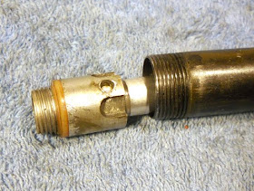
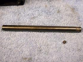
I left the ring in place when I removed the tube this time, made it much easier to remove.
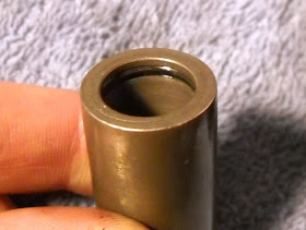
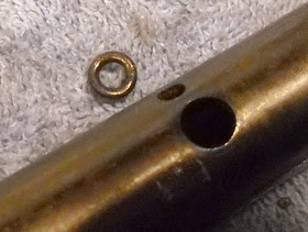
This ring is in better shape than the other. I'll pull a bunch of measurements off of it.
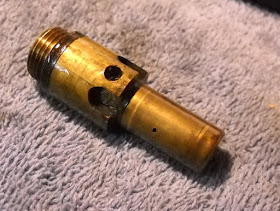
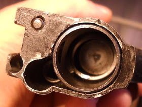
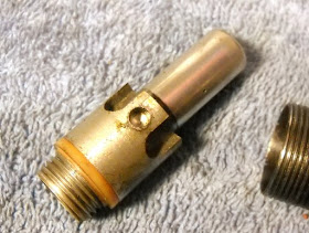
The rear valve body is made of brass on this one. See the small bleed hole on the side?
So the hammer is pushed back by gas coming from the off center hole in the end. When it reaches the bleed hole it's caught by the sear and the bleed hole bleeds off the gas inside the hammer? Sounds right.
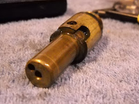
Another view. Must have been fun to set up the screw machines to make these.
Now to think about what to do with two separate piles of malfunctioning 600 parts...
Wednesday, February 10, 2010
Tuesday, February 9, 2010
Crosman Model 600 Disassembly, Part 3
On I go...
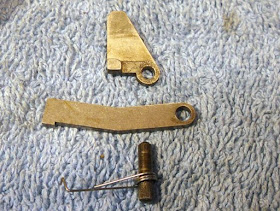
I pushed the cross pin out, keeping the punch in the hole. The buffer assembly is under a little bit of spring pressure, so I kept my thumb over it when I withdrew the punch.
The cross pin.
The buffer comes out.
The buffer and hammer spring.
Now to remove the ring (or cam ring).
I pushed against the hammer and jiggled the ring off.
Then rotated the ring so the small end could clear the slot.
The ring.
This is the main problem the pistol has. There's a lot of clearance between the square hole and the cam.
You can see how chewed up it is. I'm not entirely sure what I'll do about this yet. I could try making a new one fron scratch, or sleeving this one. Or finding a replacement somewhere. We'll see.
Then the hammer comes out.
There's an internal o-ring.
Next I inserted my largest screwdriver into the front of the tube. and unscrewed the valve front. I will be making a special tool for this, but with care the screwdriver works fine.
I found I had to reinsert a punch into the cross pin hole to get enough torque to loosen the valve front. Otherwise the tube just spins.
The valve front comes out.
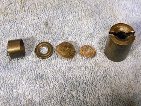
The valve front parts, screen, felt filter, washer and spacer.
Then the valve stem and spring.
I pushed the tube out the back of the frame.
The tube and frame.
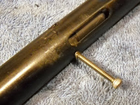
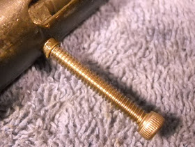
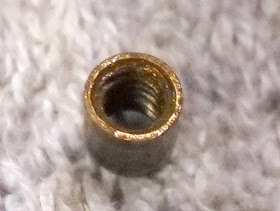
The rear valve body is retained by two blind dowel "retainer" pins that are threaded internally. I threaded a screw into them and pulled them out.
Just a close up.
A retainer pin.
Notice the o-ring at the transfer port.
The rear valve body pushed out.
Interesting off-white o-ring seal.
Then I removed the o-ring from the port. That's everything disassembled that needed it.
Next I'll be disassembling the other 600 I have and scavenging what parts it needs to make at least one fully functioning pistol, as well as measuring what I hope is an unworn ring (cam ring) so I can duplicate it. The other 600's frame has a broken trigger guard and the pistol leaks slowly but feeds and functions fine. We'll see. I'll put up pics of any differences between the two as well.
Crosman Model 600 Disassembly, Part 2
On I go...
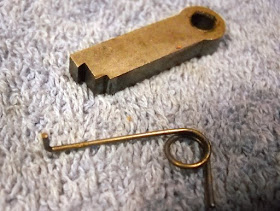
Next I removed the set screw that holds the barrel in place.
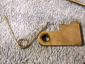
Which slides out the front of the frame.
It's easy to put a longer barrel on, as you can see.
Next I removed the safety.
The safety assembly.
I took a deep breath and removed the cover plate for the trigger.
Parts stuck to the plate which caused a few moments of head scratching.
Here's what it should look like.
Another view. You can see a line on the conical boss where one of the spring ends should rest.
And another view. You can't have too many views of complex mechanisms...There are variations on the trigger mechanism components as well between different years of the 600.
The pawl and link.
The sear.
The hammer sear?
The trigger.
Next I removed the slide screw.
And slid the slide out.
There was just a spring here when there should have been a ball and possibly a spring guide pin.
That it was bent tells me someone tried to make up for the space of a lost ball.
The slide is slightly dovetailed into the frame.
More to come...