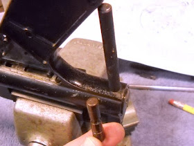
I pushed the cross pin out, keeping the punch in the hole. The buffer assembly is under a little bit of spring pressure, so I kept my thumb over it when I withdrew the punch.

The cross pin.

The buffer comes out.
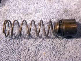
The buffer and hammer spring.

Now to remove the ring (or cam ring).
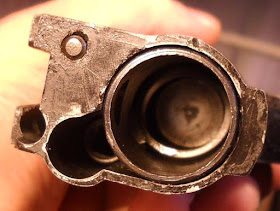
I pushed against the hammer and jiggled the ring off.

Then rotated the ring so the small end could clear the slot.
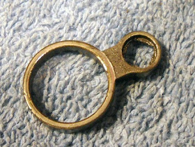
The ring.
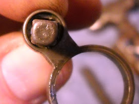
This is the main problem the pistol has. There's a lot of clearance between the square hole and the cam.

You can see how chewed up it is. I'm not entirely sure what I'll do about this yet. I could try making a new one fron scratch, or sleeving this one. Or finding a replacement somewhere. We'll see.
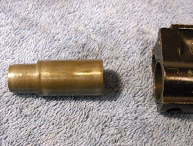
Then the hammer comes out.
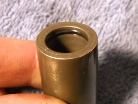
There's an internal o-ring.

Next I inserted my largest screwdriver into the front of the tube. and unscrewed the valve front. I will be making a special tool for this, but with care the screwdriver works fine.
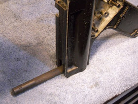
I found I had to reinsert a punch into the cross pin hole to get enough torque to loosen the valve front. Otherwise the tube just spins.
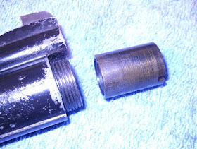
The valve front comes out.
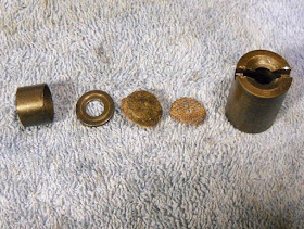
The valve front parts, screen, felt filter, washer and spacer.

Then the valve stem and spring.

I pushed the tube out the back of the frame.

The tube and frame.
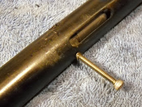
The rear valve body is retained by two blind dowel "retainer" pins that are threaded internally. I threaded a screw into them and pulled them out.
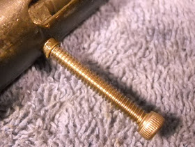
Just a close up.
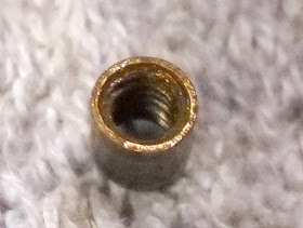
A retainer pin.

Notice the o-ring at the transfer port.
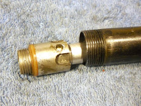
The rear valve body pushed out.
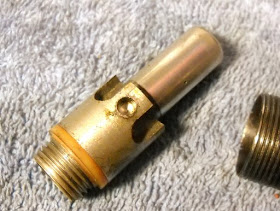
Interesting off-white o-ring seal.
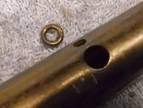
Then I removed the o-ring from the port. That's everything disassembled that needed it.
Next I'll be disassembling the other 600 I have and scavenging what parts it needs to make at least one fully functioning pistol, as well as measuring what I hope is an unworn ring (cam ring) so I can duplicate it. The other 600's frame has a broken trigger guard and the pistol leaks slowly but feeds and functions fine. We'll see. I'll put up pics of any differences between the two as well.
I'm in the process of a similar project. What did you use to pull on the dowel pins holding the rest of the valve?
ReplyDeleteId also love to know, he said a screw but no size mentioned. I’m guessing you’ll need to find the right size screw, put thread lock glue on the threads, screw it in and allow it to bond, then you’ll be able to unscrew both the locking hollow screws and the screw you put in them all at once (since they are bonded together). Then, when out and you eventually need to screw back in the 2 locking screws, first you’ll need to break the bond and separate the screw toy used. Might be worth trying without thread lock first because it might be a pain undoing it. I’m thinking I might leave the bonded screw in, cut it flush with a dremel, then notch a flathead slot in it so future removal will only require unscrewing a flathead. I do t believe those holes need open airways, I’ll investigate.
Delete