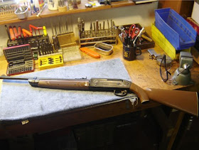
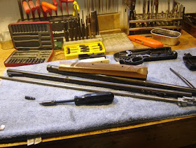
On I go.
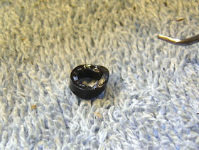
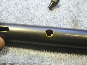
The transfer port seal was a bit rough.
So it needed to be replaced. I had one on hand.
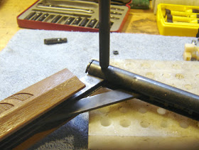
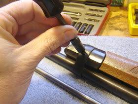
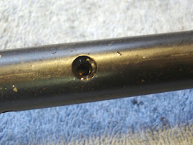
I punched out the pump pivot roll pin.
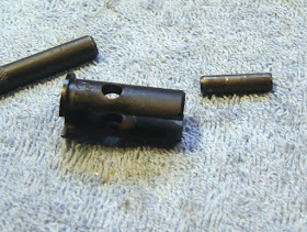
The plug and pin.
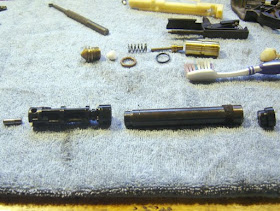
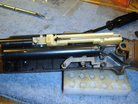
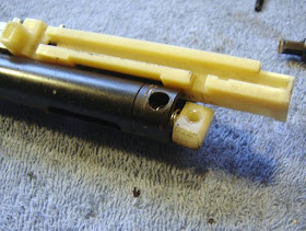
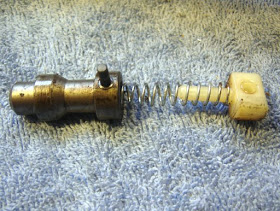
The piston assembly. It's basically a 760/1377 piston with an extension.
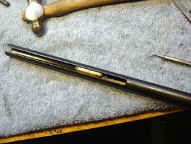
I pushed the valve out with a dowel.
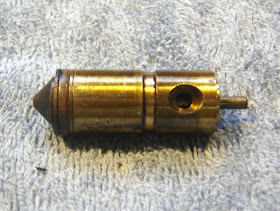
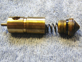
The valve.
Unscrewed.
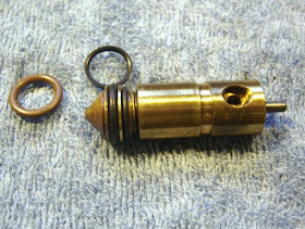
The inlet and exhaust valves were good but the o-rings needed to be replaced.
So I replaced them and screwed it back together.
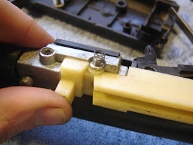
I replaced the pump cup as well. See how the extension snaps into the piston where normally the seal snaps in.
I reinserted the valve and lined up the transfer port.
You need three hands and a helper monkey to get it all back together.
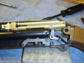
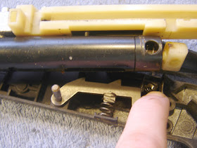
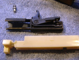
Notice the position of the cocking lever, and you have to have the BB follower pointing upwards to align with the slot it travels in. Then you sort of massage the whole thing back together. It take a couple of tries to get all the pins and such back in the holes. I'd love the see how Crosman assembles the things. I tested it and at 10 pumps I was getting 680 fps with Crosman Premier Lights (7.9gr.).
Saturday, February 28, 2009
Friday, February 27, 2009
Resealing a Crosman 2100, Part 1
Hey, I'm taking apart another airgun! The 2100 was shooting slow so I decided to see what could be done.
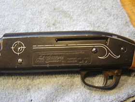
The 2100, you can download the manual and exploded drawings from the Crosman site.
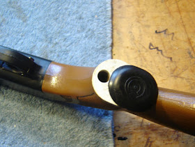
This is where you pour the BBs in. It's also where you pour them out before working on the rifle.
I removed those three screws.
Like the 760 and the 66, the gun sort of falls apart after you pry it open. It's hard to show every step because so much of the reassembly involves both hands.
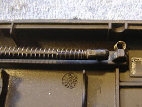
Notice the small spring (766A020) at the top fits against that cutout.
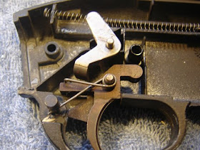
This is the way the trigger spring goes.
The sear can be retracted and the tube removed.
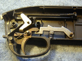
This shows the trigger relationship to the sear.
The small white plug (766-030) retains the hammer spring.
Remember that small spring? Here it is in its natural habitat fitted against the 766-019.
The bolt and 766-013 plastic thingy (Crosman doesn't give a name for it).
The hammer parts.
I unscrewed the forearm.
Mostly disassembled...more to come.
Wednesday, February 25, 2009
Short February Ramble
I'm noticing a lot of new visitors to the blog, so I thought I should mention that the Blog Index is here. It contains all but the latest posts (and they should be up on the main page). The index makes it relatively easy to find what you're looking for.
Most posts have labels at the bottom (but not my "ramble" posts). If you click on a label it will display all posts containing that label. Some labels have so many posts (like the "crosman" label) that it may not be as useful as just checking out the index.
Neither of us are professional airgun-smiths (you don't say?) and don't work on airguns for pay. We get a lot of requests for that sort of work but trust us, if you want it done professionally have it done by an established tuner/smith. You can find them by asking around on the various forums.
I have not acquired an airgun in over a month! If you have a beater sitting around that you want to get rid of, let me know! We need projects to work on for the blog. Tools, books and other airgun supplies are also welcome. We really could use a few sponsors/advertisers as well to help defray the costs.
We now return you to your regularly scheduled blog...new posts to come later this week.
Sunday, February 22, 2009
Derrick's Beeman P17 Overhaul Finale
Back to the overhaul. Time to remove the compression chamber and the valve assembly. Using a 2mm allen wrench, loosen the setscrew bearing against the cross pin anchoring the chamber to the lower grip frame shown below.
It's unnecessary to remove the setscrew. About one full turn out is sufficient.
With the setscrew loose, drive the cross pin completely out with a drift.
The compression chamber lifts right out. At the bottom of the chamber there are 3 steel "fingers" held in slots by a small cross pin. Punch out the small pin and pull the "fingers" out of their slots. Note that the center "finger" is different at the base. The small tab at the bottom guides the sear through its travel pulling the hammer. It's not a bad idea to polish the bottom guiding edge of that center finger.
Here's the compression tube. The breech o-ring can be seen near the top, left side. The valve stem is sticking out on the top right. It's a pull open valve. The hammer pulls the stem downward releasing the trapped air through the transfer port at the breech.
A 13mm wrench removes the brass nut to access the valve.
Oops. Pulled the top o-ring off already. I'm ahead of myself. The o-ring fits on the end of the valve stem in the groove. It's a #006.
I took that #006 o-ring off so I could carefully hold that end of the valve in a padded vise. A 7mm wrench removes the black nut that the hammer pulls against. The stem is peened slightly so the nut won't come off in use. Removing the nut also removes the slight peen and allows for complete disassembly.
I polished the entire valve stem on the buffer and carefully cleaned off the buffing compound. I also found a higher quality replacement hnbr o-ring (the green colored o-ring) to seal the valve circumference. Note: this o-ring is the same size as the breech o-ring.
Buzzy's Slick Honey is a superb o-ring lube--especially for sliding fit parts that still need to air seal.
The threadlocker will replace the peening I removed.
Thought I'd also teflon tape the valve nut. You know...just in case.
The PTFE tape was too wide. I cut it in half lengthwise and gave it three full wraps.
Got all liberal with the Slick Honey. Seriously, this stuff is almost impossible to wipe off. It is incredibly thin and lasts dang near forever. It was first marketed years ago by a world renown suspension tuner, Arlo Englund, as a shock bushing grease. It was first called Englund Slick Honey. Be sure to at least lube the o-rings.
Here's the reassembled valve. I didn't have a hnbr o-ring small enough for the valve seat seal. WHAT? I know. It seems impossible to me, too.
She goes back in like this.
Holding the stem stationary while threading the brass nut back in will prevent damaging that #006 o-ring.
A dental pick lifts out the breech o-ring. If better sealing against the breech was required, this is where a small super thin shim would be placed, then the o-ring reseated.
Ah yes. My green 0-friend.
Did I mention that the black nut was installed with a thread locking agent? I don't want the nut to loosen at all in use, as the hammer pulls the black nut straight down to fire the gun.
Time to reassemble. Almost as an afterthought, I decided to quickly polish the main pivot pin for the upper assembly.
Polished out. This was the pin with the small e-clips from part one.
Please refer back to the earlier post's pictures for reassembly. Essentially it goes back together as follows: First, reinstall the barrel into the top cover. The compression tube was then pinned back in place in the lower grip frame. Don't install the piston yet.
Let's put this mess back together first.
This is actually very straightforward. About 11 individual parts, but only 3 assemblies. The hammer, sear and trigger group.
Here's the hammer assembly. I lightly greased all the parts with the Buzzy's Slick Honey, then assembled the parts onto the pivot pin.
Like this.
Then, put the hammer assembly onto the valve stem and rotate it forward on the stem and into place, pressing the pin into the hole. Notice, I did not attach the small coil spring onto the lever just yet. Then, I reinstalled the torsion spring into the bottom of the hammer assembly and set the center of the spring loop onto the post molded into the grip.
Don't seat the lower end of the torsion spring. Leave the tail end of the spring hanging out the rear of the grip as shown above. Now the sear assembly can be slid into location.
Here's the sear with it's small torsion spring oriented correctly. Not shown is the pivot pin. As an aside, I should mention that in my gun--and in buddy Jason's--the hammer and sear were about as hard as glass.
I've had best luck installing the pin just far enough to go through both the spring and the sear and then sliding the sear forward through the hammer assembly. Push the sear's pivot pin into it's hole. Don't tension the sear's torsion spring.
Now is a fine time to install the trigger and trigger axis pin. No pics necessary.
Using a small pair of needle-nosed pliers, reattach the small coil spring to the hole in the lever (part of the hammer assembly) and hook the bottom loop of the spring onto the post directly below. The coil spring is directly behind the trigger if you look at the above picture.
Here's another view of that coil spring. Finally, using the needle-nose pliers, tension both the sear and the hammer torsion springs by seating their ends into the grip frame. They bear directly on the inside plastic of the grip housing. Replace the right side grip panel--taking care to align all the pivot pins, and snug down the single grip bolt with a 2.5mm allen wrench.
Pin the top cover assembly (barrel housing) back together with the long cross pin, snapping the e-clip into place. Finally, it's time to install the piston. Is the piston's #116 o-ring in perfect condition? If not, replace it and lightly lube the o-ring so it forms a positive air seal. MOST of the P17 problems will be traced back to this single o-ring. Slide the piston into the compression tube, tap the pin back in and snug down the 2mm set screw.
With this setscrew, it's done.
Shooting the gun across the chrony with a wide variety of pellets gave the following numbers:
CROSMAN PREMIER WADCUTTER ---VERY CONSISTENT
376.9, 376.1, 377.3, 379.8, 380.8, 380.6, 379.5, 379.2, 380.5, 381.5
GAMO MATCH WADCUTTERS
374.5, 383.1, 378.2, 384.5, 381.0, 385.1, 381.8, 387.5, 386.1, 387.0
BEEMAN SILVER BEAR HOLLOWPOINT ---FAST!
399.6, 399.4, 401.1, 405.3, 402.5, 403.9, 406.8, 401.3, 406.2, 411.6
And just for fun some weird ones,
WEBLEY FLYING SCOT
388.2, 369.0, 388.6, 382.8, 376.5, 380.8, 393.1, 374.5, 378.7, 384.8
BSA PYLARM
366.5, 373.8, 380.3, 385.1, 381.2, 379.6, 369.6, 392.1, 383.7, 371.7
A strange fact: While Beeman has sold this gun now for several years under 3 different model names, it's never been listed on their website.
Updated note:
I've gotten many questions about P17's dumping their air on the closing stroke. Mine started doing this the other day and I immediately assumed it was the air valve not seating. A rebuild of the air valve showed nothing was wrong and the problem continued. Close examination revealed that the sear wasn't catching the hammer consistently. Sometimes it worked fine, then--whoosh. Frustrating. It appears that the problem was the v-shaped hammer spring binding inside the grip frame. I'd put the rear end of the spring into the left grip panel on reassembly and that's not the way to do it. The tail end of the spring must be seated into the RIGHT grip panel or the spring will bind.
It's unnecessary to remove the setscrew. About one full turn out is sufficient.
With the setscrew loose, drive the cross pin completely out with a drift.
The compression chamber lifts right out. At the bottom of the chamber there are 3 steel "fingers" held in slots by a small cross pin. Punch out the small pin and pull the "fingers" out of their slots. Note that the center "finger" is different at the base. The small tab at the bottom guides the sear through its travel pulling the hammer. It's not a bad idea to polish the bottom guiding edge of that center finger.
Here's the compression tube. The breech o-ring can be seen near the top, left side. The valve stem is sticking out on the top right. It's a pull open valve. The hammer pulls the stem downward releasing the trapped air through the transfer port at the breech.
A 13mm wrench removes the brass nut to access the valve.
Oops. Pulled the top o-ring off already. I'm ahead of myself. The o-ring fits on the end of the valve stem in the groove. It's a #006.
I took that #006 o-ring off so I could carefully hold that end of the valve in a padded vise. A 7mm wrench removes the black nut that the hammer pulls against. The stem is peened slightly so the nut won't come off in use. Removing the nut also removes the slight peen and allows for complete disassembly.
I polished the entire valve stem on the buffer and carefully cleaned off the buffing compound. I also found a higher quality replacement hnbr o-ring (the green colored o-ring) to seal the valve circumference. Note: this o-ring is the same size as the breech o-ring.
Buzzy's Slick Honey is a superb o-ring lube--especially for sliding fit parts that still need to air seal.
The threadlocker will replace the peening I removed.
Thought I'd also teflon tape the valve nut. You know...just in case.
The PTFE tape was too wide. I cut it in half lengthwise and gave it three full wraps.
Got all liberal with the Slick Honey. Seriously, this stuff is almost impossible to wipe off. It is incredibly thin and lasts dang near forever. It was first marketed years ago by a world renown suspension tuner, Arlo Englund, as a shock bushing grease. It was first called Englund Slick Honey. Be sure to at least lube the o-rings.
Here's the reassembled valve. I didn't have a hnbr o-ring small enough for the valve seat seal. WHAT? I know. It seems impossible to me, too.
She goes back in like this.
Holding the stem stationary while threading the brass nut back in will prevent damaging that #006 o-ring.
A dental pick lifts out the breech o-ring. If better sealing against the breech was required, this is where a small super thin shim would be placed, then the o-ring reseated.
Ah yes. My green 0-friend.
Did I mention that the black nut was installed with a thread locking agent? I don't want the nut to loosen at all in use, as the hammer pulls the black nut straight down to fire the gun.
Time to reassemble. Almost as an afterthought, I decided to quickly polish the main pivot pin for the upper assembly.
Polished out. This was the pin with the small e-clips from part one.
Please refer back to the earlier post's pictures for reassembly. Essentially it goes back together as follows: First, reinstall the barrel into the top cover. The compression tube was then pinned back in place in the lower grip frame. Don't install the piston yet.
Let's put this mess back together first.
This is actually very straightforward. About 11 individual parts, but only 3 assemblies. The hammer, sear and trigger group.
Here's the hammer assembly. I lightly greased all the parts with the Buzzy's Slick Honey, then assembled the parts onto the pivot pin.
Like this.
Then, put the hammer assembly onto the valve stem and rotate it forward on the stem and into place, pressing the pin into the hole. Notice, I did not attach the small coil spring onto the lever just yet. Then, I reinstalled the torsion spring into the bottom of the hammer assembly and set the center of the spring loop onto the post molded into the grip.
Don't seat the lower end of the torsion spring. Leave the tail end of the spring hanging out the rear of the grip as shown above. Now the sear assembly can be slid into location.
Here's the sear with it's small torsion spring oriented correctly. Not shown is the pivot pin. As an aside, I should mention that in my gun--and in buddy Jason's--the hammer and sear were about as hard as glass.
I've had best luck installing the pin just far enough to go through both the spring and the sear and then sliding the sear forward through the hammer assembly. Push the sear's pivot pin into it's hole. Don't tension the sear's torsion spring.
Now is a fine time to install the trigger and trigger axis pin. No pics necessary.
Using a small pair of needle-nosed pliers, reattach the small coil spring to the hole in the lever (part of the hammer assembly) and hook the bottom loop of the spring onto the post directly below. The coil spring is directly behind the trigger if you look at the above picture.
Here's another view of that coil spring. Finally, using the needle-nose pliers, tension both the sear and the hammer torsion springs by seating their ends into the grip frame. They bear directly on the inside plastic of the grip housing. Replace the right side grip panel--taking care to align all the pivot pins, and snug down the single grip bolt with a 2.5mm allen wrench.
Pin the top cover assembly (barrel housing) back together with the long cross pin, snapping the e-clip into place. Finally, it's time to install the piston. Is the piston's #116 o-ring in perfect condition? If not, replace it and lightly lube the o-ring so it forms a positive air seal. MOST of the P17 problems will be traced back to this single o-ring. Slide the piston into the compression tube, tap the pin back in and snug down the 2mm set screw.
With this setscrew, it's done.
Shooting the gun across the chrony with a wide variety of pellets gave the following numbers:
CROSMAN PREMIER WADCUTTER ---VERY CONSISTENT
376.9, 376.1, 377.3, 379.8, 380.8, 380.6, 379.5, 379.2, 380.5, 381.5
GAMO MATCH WADCUTTERS
374.5, 383.1, 378.2, 384.5, 381.0, 385.1, 381.8, 387.5, 386.1, 387.0
BEEMAN SILVER BEAR HOLLOWPOINT ---FAST!
399.6, 399.4, 401.1, 405.3, 402.5, 403.9, 406.8, 401.3, 406.2, 411.6
And just for fun some weird ones,
WEBLEY FLYING SCOT
388.2, 369.0, 388.6, 382.8, 376.5, 380.8, 393.1, 374.5, 378.7, 384.8
BSA PYLARM
366.5, 373.8, 380.3, 385.1, 381.2, 379.6, 369.6, 392.1, 383.7, 371.7
A strange fact: While Beeman has sold this gun now for several years under 3 different model names, it's never been listed on their website.
Updated note:
I've gotten many questions about P17's dumping their air on the closing stroke. Mine started doing this the other day and I immediately assumed it was the air valve not seating. A rebuild of the air valve showed nothing was wrong and the problem continued. Close examination revealed that the sear wasn't catching the hammer consistently. Sometimes it worked fine, then--whoosh. Frustrating. It appears that the problem was the v-shaped hammer spring binding inside the grip frame. I'd put the rear end of the spring into the left grip panel on reassembly and that's not the way to do it. The tail end of the spring must be seated into the RIGHT grip panel or the spring will bind.