
Here's the Crosman 120. It's a .22 caliber pneumatic rifle.

Making the valve nut tool.
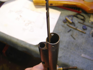
I used a some of my long drill bits to gage what width to make the slots on the wrench.
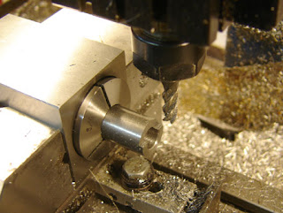
Milling the end.

The finished tool.

The valve nut.
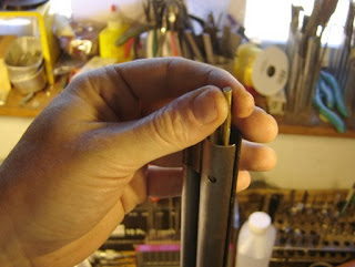
The valve wouldn't fall out so I gently pounded on the end of the inlet valve with a brass rod and an 8 oz. ball peen hammer.
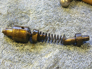
The valve came out of the valve body. Just a little oily and dirty...

I used the lathe to unscrew the exhaust valve assembly which wouldn't come apart easily. The tailstock wasn't clamped and I rotated the chuck by hand to unscrew. Then I finished unscrewing it manually.

The valve components.

The inlet valve. I like the use of a flat seal. Although replacement seals came with the rifle when I purchased it, it would be easy to make them from rubber sheet.
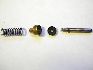
The exhaust valve. The spring is odd, the way the ends are turned back on themselves.
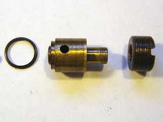
The exhaust body.
Nick,
ReplyDeleteAre you posting all these multi-pump pneumatic repairs lately to goad me into trying to fix that old 147 again? I told you, it takes witchcraft and voodoo to fix these things. I've got better odds at getting people to the moon than fixing a multi-pump.
Derrick
I know you've run out of goats to sacrifice when repairing the 147...but I know you can get it working.
ReplyDeleteBesides, I still have a number of failures mocking me in the shop...
Nick,
ReplyDeleteFailures? I thought it was all rainbows and winged unicorns whenever you worked on airguns. Seriously though, the older multi-pumps are difficult. When you don't know what the seal looked like 38 years ago, whether it was flat or convex, an o-ring or cylindrical, it gets complicated. Lord knows I've poured over a faint Crosman scan many times trying to decipher the correct orientation of some small part.
Kudos are in order anytime you can salvage another one.
So I was supposed to use goats?
Derrick
Hi,
ReplyDeletenot exactly related to this current post but I would like to find the pictures you posted a short while ago of a probe that had the front part which pushes the pellet, that looked like a semi circle.
I tried to make one similar to that but I found that unless I closed it with a snap, it tends to pushe the pellet at an angle and damages the skirt and head.
This happens because the pellet is not being pushed uniformly I presume.
Any pointers please?
Thanks and keep it up.
David.
Was it this?
ReplyDeletehttp://anotherairgunblog.blogspot.com/2008/06/1377-project-new-bolt.html
I find that some pellets, like wadcutters do hang up but the premiers feed fine. I think it has more to do with the lead in the the barrel and in my case the countersink for the breech mounting screw.
Hi ,
ReplyDeletethanks for your link, the probe I made looks very similar to the one that appears about half way down the thread,(see link below) posted by kixx.
My probe has a side cutaway that goes exactly half way round the prob's leading edge and apparently it pushes the pellet off centre as it encounters a slight resistance to engaging the rifiling. With lead being so soft, it tips sideways and gets badly deformed.
One possible solution is to reduce the cutaway about 1/4 of the way into the diameter of the probe's tip as opposed to the 1/2 way as it is now.
It is a compromise between adequate air flow and optimum pellet seating.
What do you reckon?
If it does not work I'll have to play about with extended probes that push the pellet with full contact on its base or inside skirt.
There is a picture of this kind of probe for a .25 cal barrel with a 3/16 through hole further down the mentioned thread/post, but it does not work for me.
Do you have any pictures of such setups?
Thanks for the information and keep it up.
David.
network54.com/Forum/275684/thread/1214252872/i'm+making+my+own+bolt!
It's important to remember that I have to date made exactly one bolt, so I'm not much help here.
ReplyDeleteI guess if I made a bolt tip that didn't work, I'd just make a few more and try different things until I got it to work the way I wanted.
Hi Nick,
ReplyDeleteI suppose that's the best way to go about it.
thanks anyway for the info you post for us airgun lovers.
all the best ,
david.
Nick,
ReplyDeleteDoes the locating stud (or stock screw) on the 120 models unscrew from the air tube the way that it does on the 140 and 1400 models? I have a guy who wants to sell a 120 for $30. The only hitch is that his cousin broke the locating stud on the gun.
I can't remember, but I'm 90% sure it does unscrew.
ReplyDeleteFelice,
ReplyDeleteThanks for helping :)
I bought the gun even with the broken stud (and missing bead and missing rear sight elevation screw) and now have it in my garage. The collar appears to be welded to the air tube. I tried to unscrew it (carefully) with luck. So, plan B. I am going to try to drill out the threaded rod and simply replace it. It is a simple threaded rod -- 1/4-28. Now to find a parts store locally that can sell me one.
The sight bead isn't a must have, so the next thing will be to find a screw for the rear sight. Of course, it will also need new seal most likely, sigh. This "bargain" could eventually get pretty expensive. ;)
Does the stock locating screw also hold the valve assembly in,I've hit at it from both sides and doesn't seem to move at all
ReplyDeleteNot sure, if you look at the next post, I show a hole opposite the exhaust hole, perhaps yours has a screw holding it in the tube?
ReplyDeleteOnly screws remaining are the two to rear sight and the stock locating allthread
DeleteWell the service manual is a bit vague:
ReplyDelete1. Remove Knurled Locating Screw Nut
from under stock.
Remove Stock.
2. Clamp Tube in protected Vise Jaws. Do not
put strain on Breech, breech side down.
Remove Spring Stop Screws (110-31).
Remove Spring Stop Bottom Screw (110-12).
Remove Hammer Spring Stop (105-24).
Remove Hammer Spring Guide (110-29).
Remove Hammer Spring (110-7).
Remove Hammer (110-20).
Remove Cocking Pin (113-59).
Remove Breech Bolt (114-6).
Remove Breech Bolt Lock Assembly (110-64).
3. For removing Valve System refer to
details Page 2-A, Item 5 and drawing Page 2.3
4. Drive out Front Sight Pin (110-15).
Remove Front Sight (105-26)
Remove Pump Assembly (140-74).
Refer to Drawing Page 3.1.
So section 2 is on the 108-109, and says:
DISASSEMBLY PROCEDURE FOR AIR RIFLE MODELS 107-108 REFER TO DRAWINGS PAGE 2.1, 2.2, 2.3
1. Remove Rear Stock Screw (108-21).
Remove Knurled Locating Screw Nut from under
side of stock.
Remove Stock.
2. Clamp unit in vise on Breech Block (108-1).
Unscrew Breech Bolt Lock Screw (105-53).
Remove Breech Bolt Lock Assembly.
3. Remove Spring Stop Screws (108-22).
Remove Spring Stop (108-9).
Remove Hammer Spring (108-28).
Remove Hammer (108-8.
4. Remove Cocking screw (108-15) thru slot in Tube.
Remove Breech Bolt (108-6) CAUTION; Breech
Bolt Spring Balls (105-39) and Breech Bolt
Spring (105-40) may fall out when Breech
Bolt is removed.
5. Remove Valve Nut (110-18) using Special Wrench T-l). Exhaust
Valve Body must be held in position with line up pin (T-3) in blind hole
provided for this purpose, while unscrewing Body Lock Nut.
Remove Exhaust Valve Body Assembly from Tube
with threaded portion of Valve Extractor (T-5).
Shake out Check Valve Assembly (108-73).
Shake out Check Valve Spring (101-43).
NOTE: If Exhaust Valve Body Gasket (105-31)
adheres to Chamber, it can be picked out with
wire hook. Refer to drawings Page 2.3 for
Valve Assembly detail.
6. Drive out Front Sight Pin (110-15).
Remove Front Sight & Guide Assembly.
Remove Pump Assembly (140-74).
Refer to Drawings Page 2.2
NOTE: Compression Chamber (105-23) and Locating Screw is soldered into Tube (108-26). Breech (108-1) is soldered to Compression Tube (108-26).
But perhaps yours has been modified or is a variant?
ReplyDeleteAsk on the Vintage airgun forum (tapatalk) or a Crosman forum
https://www.tapatalk.com/groups/americanvintageairguns/american-vintage-airguns-f405945/
Iv kinda got the same problem Got a model 1400 with the locating stud welded to the tube won't hold air it is hisses out every time I pump it
ReplyDeleteHello good morning, does anyone know which side the valve comes out of the Crosman C120?
ReplyDelete"The valve wouldn't fall out so I gently pounded on the end of the inlet valve with a brass rod and an 8 oz. ball peen hammer."
ReplyDelete