Alternative title: Derrick's frustration with cold blue finishes.
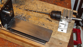
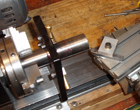
I thought the single taper looked too plain. The muzzle weight was a bit too boxy and formless for my taste. I cut a second taper for no good reason--except I wanted it to look a bit different. I was also fighting the compound slide's tendency to "rock" as it has only a single anchor point. I found that an extra tool post (the small black rectangle with the allen bolt in the middle) makes for a perfect secondary clamp to keep the compound firmly anchored to the cross slide. Rock gone, I continued cutting metal.
Not shown, I cut a few shallow grooves to add something else to look at.
Centered up and bolted down a V block to the drill press table. Spotted and drilled two holes for setscrews. Decided to use M5 x 0.8mm threads as Joe verified that he, indeed, has small metric allen wrenches. I believe the wrench size was a 2.5mm for the allen heads. To calculate the tapping drill size for METRIC threads, take the diameter and subtract the pitch. 5 - 0.8 = 4.2 mm to use for the drill bit size.
I saw this somewhere, either in Home Shop Machinist or Machinist Workshop. I chucked the M5 tap into the drill press and clamped a tap handle around the smooth body of the tap. Power off, and belt disengaged, I lowered the drill press and started turning the plug tap by hand. The idea is that this set-up aligns the tap in the vertical hole just made.
I thought it worked well, but I could've used a third hand. At some point, the tap handle does slip on the tap body, but at that point, the thread is started and can be finished out of the drill press by hand. As always, tapping oil is your best friend.
Here's where things went downhill. I cold blued the weight using my personal favorite Formula 44/40. After bluing, I oiled the part--and most of the blue came off leaving a thin gray color behind. Ack! I stipped the part on a brass wheel and tried Birchwood Casey Super Blue. The color took well, but seemed a rather bright blue with not enough black. I knew it wouldn't match the metal on the 850 Air Magnum so it got stripped off. I went back to the 44/40 and burnished it into the metal using almost dry patches.
The finish was a remarkable, even matte color. I oiled it lightly and took it over for a test fit on the gun. It was too small on the bore ID by about 0.002". What? You think these projects always go well the first time? Not in real life. At least not in mine. Dejectedly went home, and bored out the end a few extra thou to be on the safe side. Touched up and lightly oiled the finish. Next day, the weight looked good, so it got a more liberal coat of oil. 10 Hours later, it was absolutely covered in a fine layer of brown rust. I gave up on the finish. I hit it on a brass wheel yet again and gave it a quick shine with Mother's Mag Polish.
A second test fit and this time, it fit perfectly on the gun and we shot a couple magazines to verify POI.
My cohort will likely strip his bolt handle as well to match and he'll either keep a thin coat of oil or wax on the bare steel surfaces.
The brake ended up at exactly 7 oz. of additional weight for the muzzle.
So: I've come to the conclusion that there are some alloys of steel that just don't seem to "like" certain cold blues. A muzzle brake on another gun was finished with 44/40 over a year ago and it still looks like it was factory finished. Yet, other items have had flash rusting problems with Perma Blue, Super Blue and Dicropan T-4. A quick net search revealed that this is often a problem with cold blues and some will actually promote further rusting. If I can pry the brake away from my co-worker, I may try the 44/40 again, but rinse it thoroughly for about a half an hour in cold water, then immersing it in oil for a couple of days. My friend feels bad that I did all this work for such a simple thing. What he doesn't realize is that I learned more from the problems this time than from the successes. And sometimes that's just the way it goes.
Saturday, April 4, 2009
Monday, March 30, 2009
Muzzle Weight For Derrick's co-worker Part 1
At the "Toys that Shoot" airgun show in Findlay, OH last year, a cohort bought a .22 cal Hammerli 850 Air Magnum from the nicest guy in the airgun industry, Ron Sauls. As a shooter, the gun is an absolute bell ringer. After scoping the gun and removing the front sight, he wanted a muzzle brake or weight of some sort. My old Beeman ribbed aluminum weight wasn't cutting it. It was too light and the gun's balance point was too far rearward. The Air Magnum is a lightweight gun to begin with, and we both agreed that some additional weight at the business end would allow for a steadier hold.
I started with a piece of 1" diam. drill rod.
Cut off a 5.75" piece. Didn't weigh it. It was easily over a pound of steel.
With the steady rest in place, I faced both ends.
Spotted one end with a center drill.
Note to self: Drilling a 5" hole in a piece of solid steel is really a drag. It would take one heck of a drill press to do this. The lathe spins the workpiece, the tailstock holds the drill bit stationary.
The swarf was piling up.
This was the happiest moment of my day. A 0.250" hole--and it looks on center!
The 0.250" hole will allow a .22 cal pellet to pass through. Now I need to open up one end to fit over the muzzle. A quick call this morning to Joe reminded me that there are several screw holes for the front sight base that I need to cover. Need the bore to be a bit over 2.400" long. The Air Magnum's barrel, by the way, is 0.5905"diameter. (15 mm) Great, that's huge. I don't have a drill bit that large that will fit in the tailstock. I started to drill with a short 1/2" drill bit.
More swarf. I drilled the half inch hole 2.80" into the end.
Then, full stop. I didn't have a 15 mm drill bit and I didn't have a boring bar long enough. This is the fun part of machining--you often need to make tools to use your tools. Yep. Whee!
A not-so-quick side project: a boring bar. Grabbed a piece of 0.250" drill rod from the pile and cut a piece about 4" long.
Faced both ends. I would have done some layout and actually done some measurement, but I was burning daylight. A quick trip to Kromhard Twist Drill Company netted me a small boring bar cutting insert.
I eyeballed the insert's base angle and hand filed it into the end of the drill rod.
What's the worst that could happen? Not shown: I laid the insert into the notch, spotted the center of the hole for the fixing screw, consulted a tapping chart, drilled the tap clearance hole with a #47 drill bit, hand tapped the hole to 3-48, heated the bar to cherry red with a torch , quenched it, and I was in business. No, wait. I don't have a boring bar HOLDER in this size. Gotta make another tool to use the tool.
This is a really handy adapter. It threads directly to the Taig lathe's headstock, and allows attachment of a Jacobs chuck.
Here.
I decided to modify an existing tool post to hold the boring bar. I know the boring bar is 0.25" diam. and half of that is 0.125". I dialed out the caliper to a slightly larger number. (Didn't want the edge of the 0.25" hole to come though the side of the holder.) Also had to make sure I didn't drill into the tool post anchor bolt in the center. Settled on 0.150". Set one jaw of the caliper against the aluminum tool post and scratched a reference line. I'll line up the center of my 0.25" hole on this line.
Squared up the tool post on the lathe's cross-slide and bolted it down. Chucked a center drill into the Jacob's chuck, aligned with my scored line, and spotted the hole.
Drilled through with a 0.125" bit...
Followed by a 0.25" bit. I followed this with a chucking reamer to make sure the hole was round and to the correct size.
Spotted 2 holes for 8-32 set screws. Tapping drill #29.
Ran the plug tap in by hand. Lots of cutting oil.
OK, I blued the boring bar.
Back to work. For eyeballing all the angles, the bar worked just fine.
You need a clearance hole for the boring bar to work. Rotated the bar in the holder to get the cutting edge on center. Snugged down the set screws. I used a lot of cutting oil. I bored the hole to just over 0.595". A couple high speed passes just kissing the surface left a nice interior finish.
When I pulled the piece from the lathe, I was astonished to find it still weighed 13.4 oz. I don't think my co -worker had that kind of weight in mind. So, chop. Cut the front end off. Now it's 4.80" OAL and down to 7.62 oz.
I need a metal cutting bandsaw.
Faced the end off using another tool I made a few days ago...
Used the boring bar again to make some cuts into the muzzle end of the weight.
Decided to try out the new live center. Just took a passing cut.
Back to the steady rest again to minimize deflection. To cut a taper on the rear of the brake, I set up the compound slide.
Picked an angle and started with some very light cuts.
Even the light cuts were pulling the workpiece out of the 3-jaw chuck. I switched to the steel 4-jaw, got out a dial indicator, centered the workpiece.
Slowly cutting the taper.
Another view.
More soon...
Early Crosman Model 101 Disassembly, Part 3
Just a little more for now.
The end of the plunger.
Finding an edge.
Drilling two holes to match the spacing on the plunger.
Two pins pressed in.
Unscrewing the plunger.
Done.
I don't think the leather compression ring is supposed to be built up out of three parts as the drawing I have shows it made of 1/4" thick leather. The expander ring is rusted horribly and will need to be replaced.
Unscrewing the rest of the assembly.
That is a solid piece...
The felt was pretty rotten. I think I have a spare.
You can see that there is space for the expander ring near the end.
As far as I can tell, on the pressure stroke air enters through those holes forcing the leather against the sidewall assisted by the expander ring. As it is withdrawn the expander ring ,being springy, compresses enough to allow air by. I'll be blogging more about that when I get to the point of rebuilding the plunger.
Now to just find the time to put it back together.