This post shows the results of being distracted at a critical time.
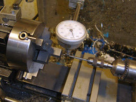
I chucked up a piece of L shaped steel in the 4 jaw chuck.
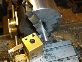
Turned a shaft on it.
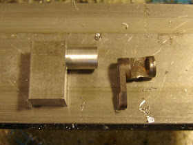
Looks like a safety already.
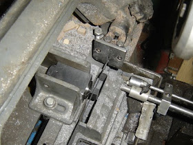
Sawed off the waste.
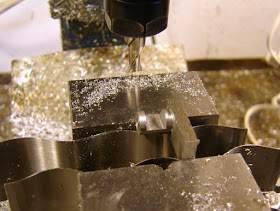
I put it backwards in the vise, alas, when cutting the notch for the safety plug.
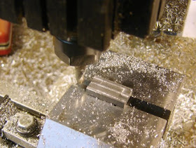
Milled it thinner.
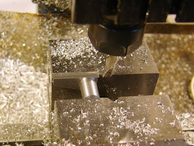
Trimming away.
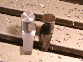
A rough, mirror image safety.
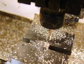
I rounded the corners on the belt sander, then milled away a bit more to make the lever.
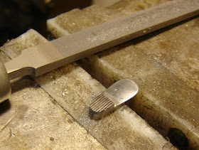
I used the checkering file to serrate the lever.
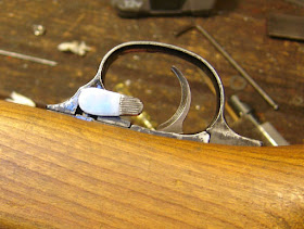
Well, it works, but it's the wrong way around.
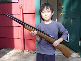
This is the guy who distracted me. But he makes a good gun rack.
There's still a bunch to do, assuming I can live with a backwards safety lever.
I drew up the bolt today, and hope to make it this weekend. Then I'll think about the final design for the breech cover.
I did run some rounds through the gun. Initial numbers were in the low 300's, at which point I realized I was loading .177 pellets in a .22 rifle. Distractions...anyway, it's shooting around 580 fps with 10 pumps (14.3 gr.), which is a little low. I hope that a new transfer port seal and a new bolt will speed it up a bit. We'll see.
Friday, October 24, 2008
Wednesday, October 22, 2008
Getting a Crosman 140 Working, Part 3
So, I continue doing the minimum work to get the rifle to function.
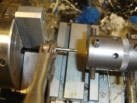
I turned and threaded a new breech bolt. I just winged the dimensions. Because I used the 3 jaw chuck the bolt slipped a bit while I was threading it. So I grabbed onto the waste stock with some vise grips.
As you can see it wasn't a particularly accurate copy, better to follow my detailed article on how to make one exactly, but for less than 10 minutes of machining it's fine to test the rifle.
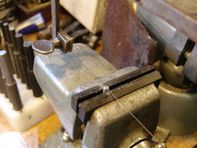
Slotting the screw head with a jewelers saw.
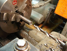
Drilling some 1/2" steel stock.
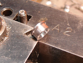
With a flange turned and parted off. I made a thick washer from the same stock.
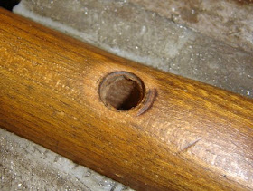
The insanely large stock screw hole. It shouldn't be that big?
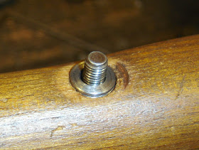
Flanged bushing and washer in place. I used a nut to clamp the stock but will make a knurled nut soon.
The rifle is now complete enough to test, although there's clearly a lot of work remaining...more posts to come...
Tuesday, October 21, 2008
Getting a Crosman 140 Working, Part 2
So having stuffed the valve back together, I needed to test the rifle. Which meant making a few parts...
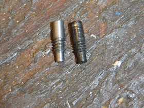
I had to cut down a screw to hold the trigger group in the front. Threading a nut on the screw above the cut allows you to reshape the threads after sawing and deburring.
The bolt will get replaced (due to the front end being broken), but I wanted to test the valve first...so I have to remove the broken screw in the bolt.
I spot drilled the screw.
And drilled it out.
My Crosman 130, which also uses a sliding breech cover. I decided to use it for the appropriate dimensions on a temporary breech cover.
A piece of 3/4" steel cleaned up.
Drilled out to 5/8" and then bored a few thousandths.
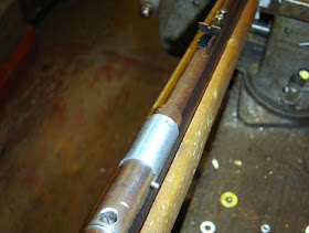
Tube and the 130 cover.
I haven't had a gratuitous edge finding picture in a while. I found center and then the location of the hole for the breech screw.
Spot drilled and then drilled.
Milling away a little under half of the cover.
A line was scribed to show where to mill away the cover so it would rest on that pin.
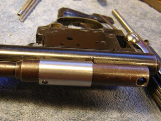
Milled and reassmbled with a new bolt o-ring. A lot of work for a temporary fix, but it didn't take that long, and I didn't want to do a lot of work before I tested the function of the valve...
Monday, October 20, 2008
Getting a Crosman 140 Working, Part 1
Well, I bought another "pile-o-parts" airgun, a Crosman 140. It was mostly in pieces so I took everything else apart and cleaned the gunk off.
The main parts. Not shown are the pump components, stock, tube and the barrel
The valve. It's a pop-off valve, held under pressure by the sear. When the trigger is released the cap at the right pops off and releases the air.
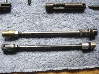
The piston rod that came with the rifle is at the bottom. Someone tried unsuccessfully to remove the old seal, and did what looks like a bunch of grinding on it. The top rod assembly came as a spare with the Crosman 101 pile-o-parts I bought a while back. So I figured that I'd use it instead.
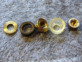
The 101 piston parts, and a new seal that also came with the 101. Since I'm nowhere near close to working on the 101 I figured I'd use it here.
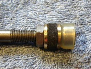
The new piston head.
The valve o-rings were removed and replaced with new ones. The pop off valve has an internal quad seal. Later on in the process I ended up replacing it with an o-ring which will probably not last. I'll be ordering in the proper seal soon.
The assembled valve. Those marks were made by the previous owner. Really...
The valve is held in by the stock screw. I wish it had flats on it for a wrench.
The pivot pin is a spring pin. How I hate pushing it in and out when setting the optimum piston rod distance, as well as getting the valve assembled correctly.
The trigger group looks a lot like the 160 trigger, but is simpler as it only retains the "hammer" against the valve pressure. The front screw holding it to the tube is temporary. I didn't bother putting the barrel on yet.